Method for monitoring activity state of underground fault
What is AI technical title?
AI technical title is built by PatSnap AI team. It summarizes the technical point description of the patent document.
A technology of active states and faults, used in geophysical measurements, instruments, etc.
Inactive Publication Date: 2014-04-30
KUNMING UNIV OF SCI & TECH
View PDF0 Cites 9 Cited by
Summary
Abstract
Description
Claims
Application Information
AI Technical Summary
This helps you quickly interpret patents by identifying the three key elements:
Problems solved by technology
Method used
Benefits of technology
Problems solved by technology
[0003] The invention provides a method for monitoring the active state of an underground fault, which is used to solve the problem of correctly and timely predicting the displacement, stress, and the location and area of the active state of the fault under the influence of mining.
Method used
Image
Click on the blue label to locate the original text in one second.
Reading with bidirectional positioning of images and text.
Examples
Embodiment 1
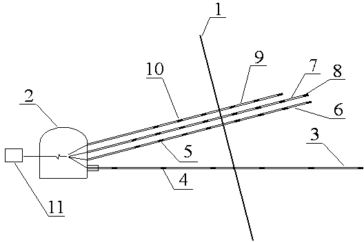
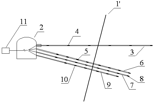
[0022] Embodiment 1: as Figure 1-2 Shown, a kind of downhole fault active state monitoring method, the concrete steps of described method are as follows:
[0023] A. Excavate observation chamber 2 in the footwall of normal fault 1 or the upper wall of reverse fault 1′;
[0024] B. Arrange horizontal medium-deep holes in the observation chamber 2, wherein the medium-deep holes pass through the fault plane for a certain distance S 1 And a multi-point displacement gauge 3 is installed in the middle and deep holes;
[0025] C. Arrange three medium-deep holes perpendicular to the fault plane, among which the medium-deep holes pass through the fault plane for a certain distance S 2 And the anchor multi-point stress gauge 6, the drilling multi-point stress gauge 7, and the microseismic monitoring system 9 are respectively installed in the three medium and deep holes;
[0026] D. Multi-point displacement meter 3, bolt multi-point stress meter 6, drilling multi-point stress meter...
Embodiment 2
[0036] Embodiment 2: as Figure 1-2 Shown, a kind of downhole fault active state monitoring method, the concrete steps of described method are as follows:
[0037] A. Excavate observation chamber 2 in the footwall of normal fault 1 or the upper wall of reverse fault 1′;
[0038] B. Arrange horizontal medium-deep holes in the observation chamber 2, wherein the medium-deep holes pass through the fault plane for a certain distance S 1 And a multi-point displacement gauge 3 is installed in the middle and deep holes;
[0039] C. Arrange three medium-deep holes perpendicular to the fault plane, among which the medium-deep holes pass through the fault plane for a certain distance S 2 And the anchor multi-point stress gauge 6, the drilling multi-point stress gauge 7, and the microseismic monitoring system 9 are respectively installed in the three medium and deep holes;
[0040] D. Multi-point displacement meter 3, bolt multi-point stress meter 6, drilling multi-point stress meter...
Embodiment 3
[0050] Embodiment 3: as Figure 1-2 Shown, a kind of downhole fault active state monitoring method, the concrete steps of described method are as follows:
[0051] A. Excavate observation chamber 2 in the footwall of normal fault 1 or the upper wall of reverse fault 1′;
[0052] B. Arrange horizontal medium-deep holes in the observation chamber 2, wherein the medium-deep holes pass through the fault plane for a certain distance S 1 And a multi-point displacement gauge 3 is installed in the middle and deep holes;
[0053] C. Arrange three medium-deep holes perpendicular to the fault plane, among which the medium-deep holes pass through the fault plane for a certain distance S 2 And the anchor multi-point stress gauge 6, the drilling multi-point stress gauge 7, and the microseismic monitoring system 9 are respectively installed in the three medium and deep holes;
[0054] D. Multi-point displacement meter 3, bolt multi-point stress meter 6, drilling multi-point stress meter...
PUM
Abstract
The invention relates to a method for monitoring the activity state of an underground fault, and belongs to the technical field of mining disaster monitoring. The method comprises the steps that an observation chamber is dug in a forward fault footwall or a reverse fault upper wall at first; horizontal medium-length holes are distributed in the observation chamber, the medium-length holes penetrate through the fault surface by a certain distance, and multipoint extensometers are mounted in the medium-length holes; an anchor rod multipoint stress detector, a drilled hole multipoint stress detector and a micro-seismic monitoring system are mounted on the position perpendicular to the fault surface; the displacement changes of the upper wall and the footwall of the fault, the additional tensile stress states of different positions away from the fault surface, additional shear stress states of different positions away from the fault surface, broken positions in the mining activity process and area data information of the fault can be monitored by collecting and processing the data in real time, and then the data are directly transmitted to a ground surface monitoring center. The method can monitor the displacement changes of the upper wall and the footwall of the fault, the states of additional tensile stress of the different positions away from the fault and perpendicular to the fault surface, the states of additional shear stress parallel to the fault surface, and the like in real time.
Description
technical field [0001] The invention relates to a method for monitoring the active state of an underground fault, and belongs to the technical field of mining disaster monitoring. Background technique [0002] Faults, as low-strength zones in rock bodies, are often activated by mining. The activation of faults will cause relatively strong deformation and damage to the surrounding rock of the shaft, and the sudden relative displacement of the two plates of the fault and the sudden release of elastic strain energy due to mining activities often cause mining dynamic disasters such as mine earthquakes, which bring serious damage to the mine. Therefore, it is necessary to find a monitoring method of fault activity status, make a correct prediction of the fault activity status, and make a timely prediction of the sliding instability of surrounding rock induced by fault activation under the influence of mining. Contents of the invention [0003] The invention provides a method f...
Claims
Application Information
Patent Timeline
Application Date:The date an application was filed.
Publication Date:The date a patent or application was officially published.
First Publication Date:The earliest publication date of a patent with the same application number.
Issue Date:Publication date of the patent grant document.
PCT Entry Date:The Entry date of PCT National Phase.
Estimated Expiry Date:The statutory expiry date of a patent right according to the Patent Law, and it is the longest term of protection that the patent right can achieve without the termination of the patent right due to other reasons(Term extension factor has been taken into account ).
Invalid Date:Actual expiry date is based on effective date or publication date of legal transaction data of invalid patent.

