
Charging method and control module of battery charging unit and battery charging unit

A battery charging and control module technology, applied in battery circuit devices, electrical components, current collectors, etc., can solve the problems of short maximum stroke, high cost, limited battery charging capacity, etc., and achieve the effect of reducing current demand and improving utilization rate

Inactive Publication Date: 2014-04-30
INESO
View PDF4 Cites 0 Cited by
  • Summary
  • Abstract
  • Description
  • Claims
  • Application Information

AI Technical Summary

Problems solved by technology

However, there is a problem with electric vehicles in the prior art that the charging capacity of the battery installed on the electric vehicle is relatively limited, resulting in a relatively short maximum range compared with a vehicle with an internal combustion engine
However, the cost of building such a wide range of dedicated charging stations is prohibitive

Method used


Image

  • Charging method and control module of battery charging unit and battery charging unit
  • Charging method and control module of battery charging unit and battery charging unit
  • Charging method and control module of battery charging unit and battery charging unit

Examples


other Embodiment approach

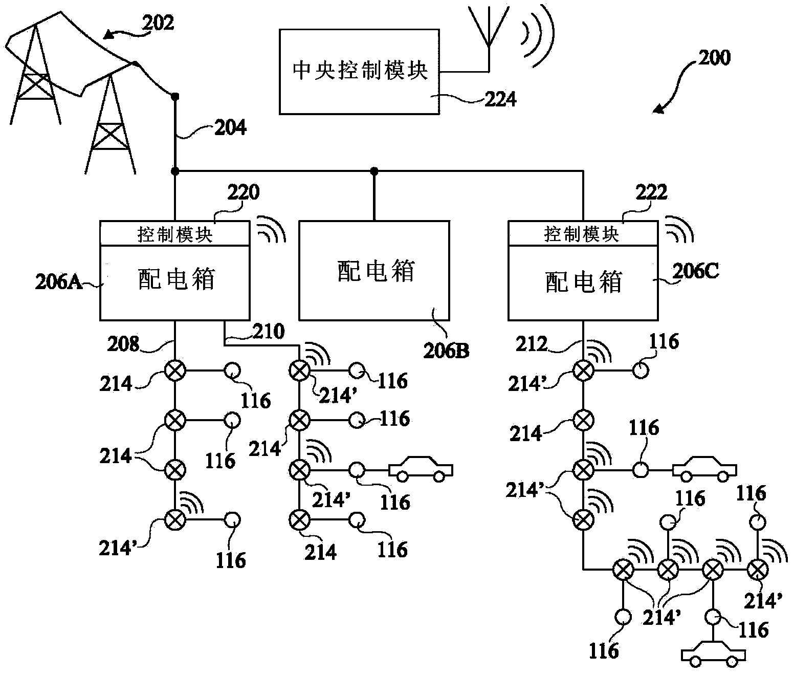
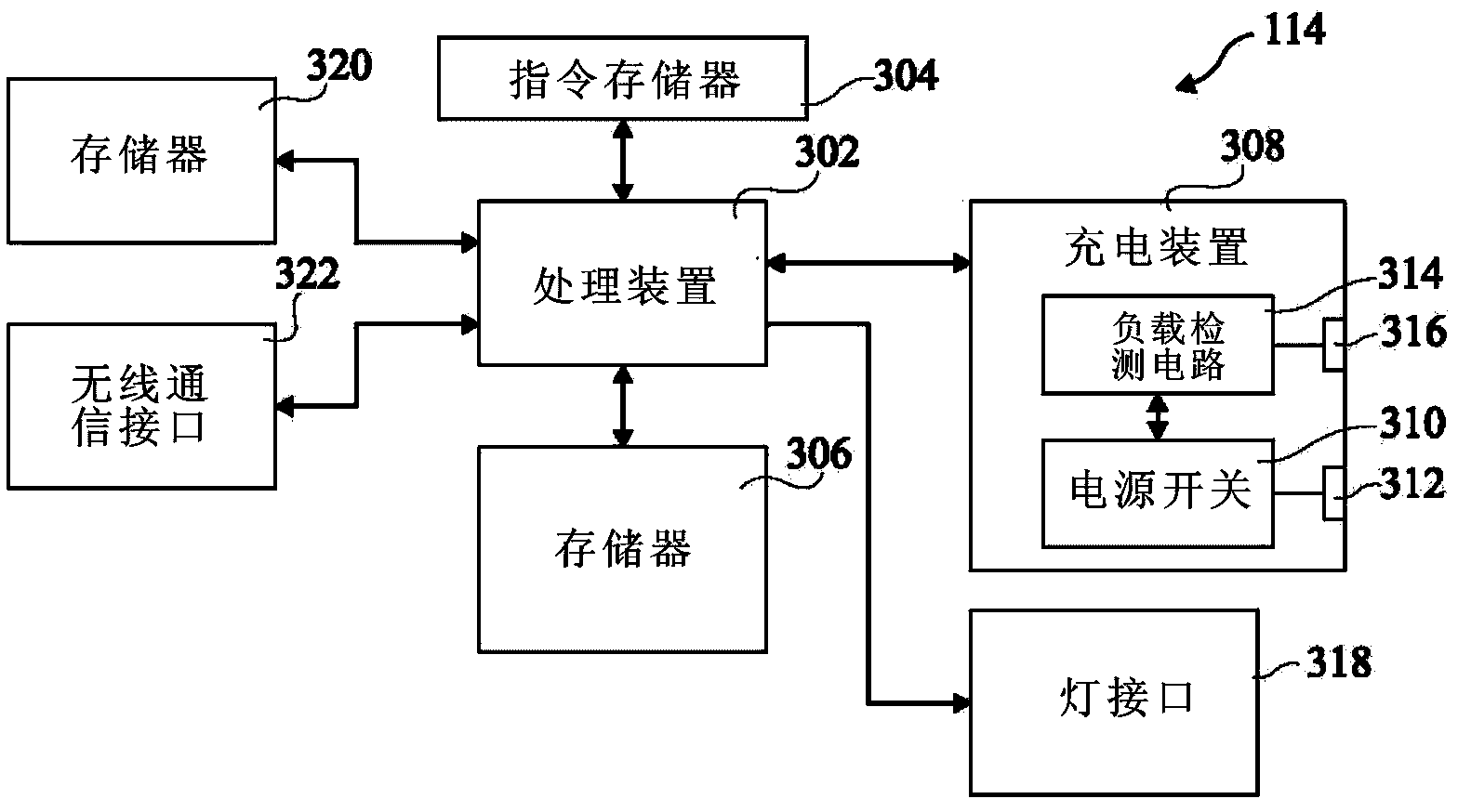
[0042] In other embodiments, the power distribution line connected to the charging unit 114 can be identified according to the location data information and / or according to the identification code of the charging unit. The maximum current limit of the identified distribution line is then used to determine whether to accept or deny the request. The maximum current level includes factors such as the resistance of the wires forming the distribution line. The control module includes access to data showing the level of current flowing from the distribution line at any given time. In addition, each control module is capable of storing a reading of the maximum authorized current on each distribution line it supplies. For example, the maximum current limit can be in the range of 10 amps to 32 amps, assuming that the requested current is IR, the current flowing in the distribution line is ID, and the authorized maximum current level in the distribution line is IMAX, the request , the...


PUM


Abstract

The invention discloses a charging method of a battery charging unit. The charging method of the battery charging unit comprises the following steps that a request of a first current flowing in through a power distribution line is received from a first battery charging unit through a control module, the control module has access to position data information of the position of the first battery charging unit in the power distribution line, and displays the position data information, and the control module generates instruction information indicating that the request is accepted or rejected for the first battery charging unit. The invention further discloses the control module of the battery charging unit and the battery charging unit. According to the charging method of the battery charging unit, the control module of the battery charging unit and the battery charging unit, charging can be carried out batteries of vehicles such as electric vehicles through existing power supply infrastructure, the utilization rate of lighting networks is improved, and the requirement of the lighting networks for currents is greatly reduced.

Description

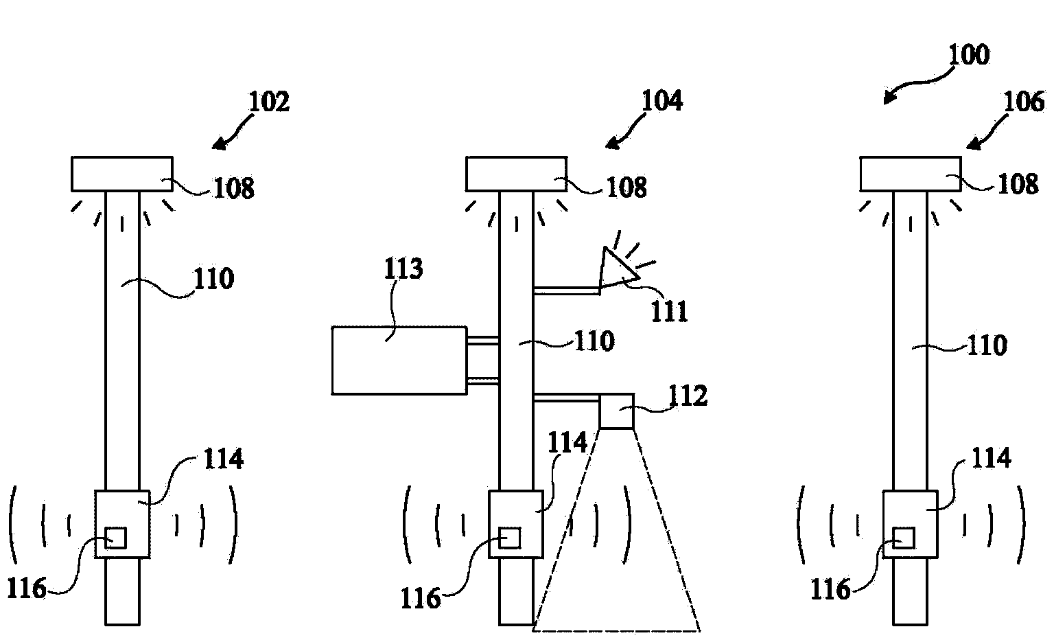
technical field [0001] The invention relates to the field of charging lighting, in particular to a method for controlling one or more battery charging units connected to a power distribution line, a control module and a battery charging unit. Background technique [0002] Electric vehicles are cleaning equipment for fossil fuel powered vehicles. However, there is a problem with the electric vehicle in the prior art that the charging capacity of the battery mounted on the electric vehicle is relatively limited, resulting in a shorter maximum range compared with a vehicle with an internal combustion engine. [0003] Based on the limited maximum range of electric vehicles, encouraging the popularization of electric vehicles requires regular charging stations along the highway. However, the cost of building such a wide range of dedicated charging stations is prohibitive. [0004] In summary, it is necessary to use the existing street lighting network to charge electric vehicle...

Claims


Application Information

Patent Timeline
IPC IPC(8): H02J7/00H02J7/02
Inventor 戴福兵
Owner INESO
Learn More