Suspension device
A technology of suspension device and installation part, which is applied in the direction of suspension, elastic suspension, transportation and packaging, etc.
- Summary
- Abstract
- Description
- Claims
- Application Information
AI Technical Summary
Problems solved by technology
Method used
Image

Examples
no. 1 Embodiment approach
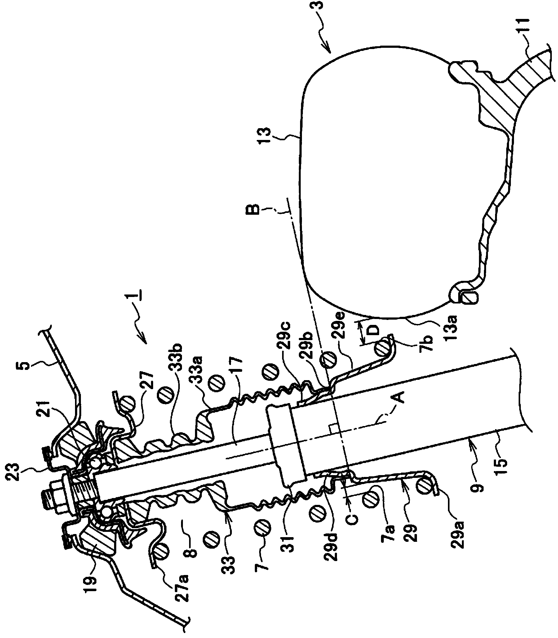
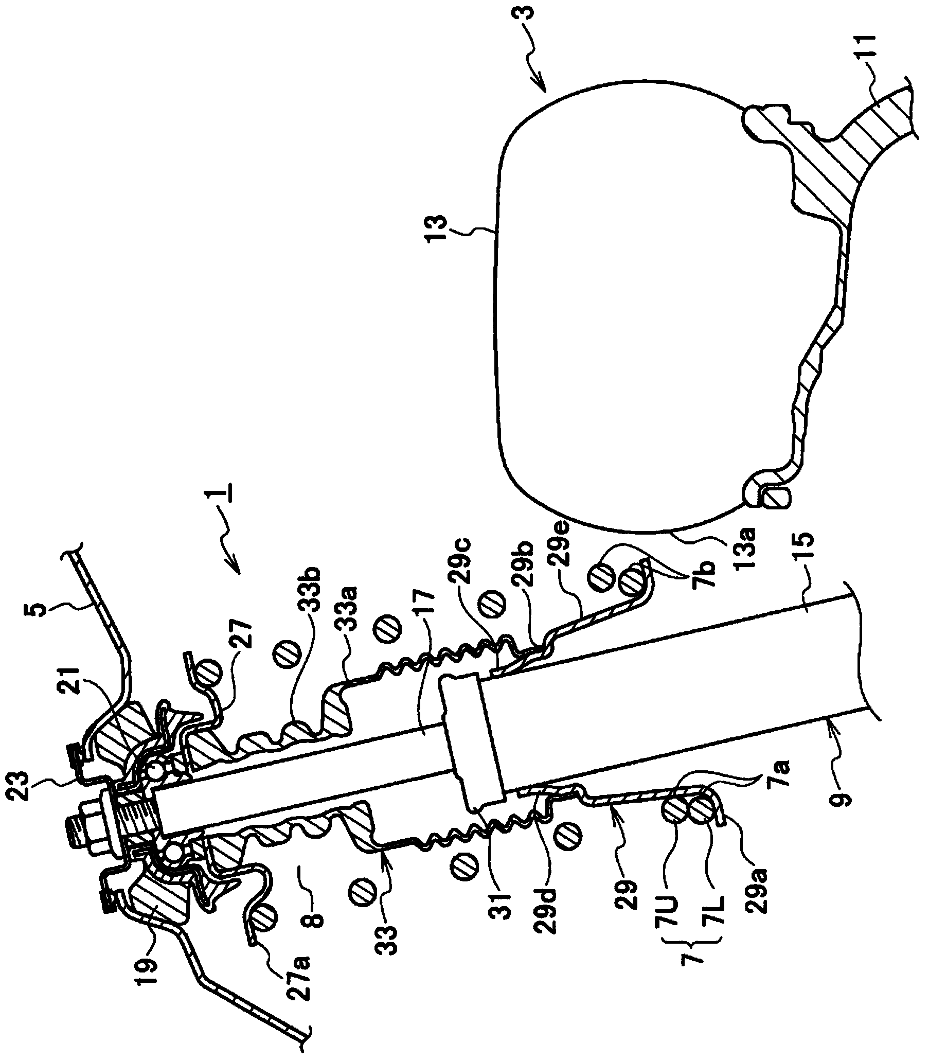
[0015] figure 1 It is a cross-sectional view of the suspension device 1 according to the first embodiment of the present invention. This suspension device 1 has: a coil spring 7 which elastically receives the up and down movement of the wheel 3 relative to the vehicle body 5; . The tire 13 is located on the outer side in the vehicle width direction near the lower end of the coil spring 7 ( figure 1 on the right side of the ). Here, the wheel 3 is composed of a hub 11 on the inner peripheral side and a tire 13 mounted on the outer peripheral side of the hub 11 .
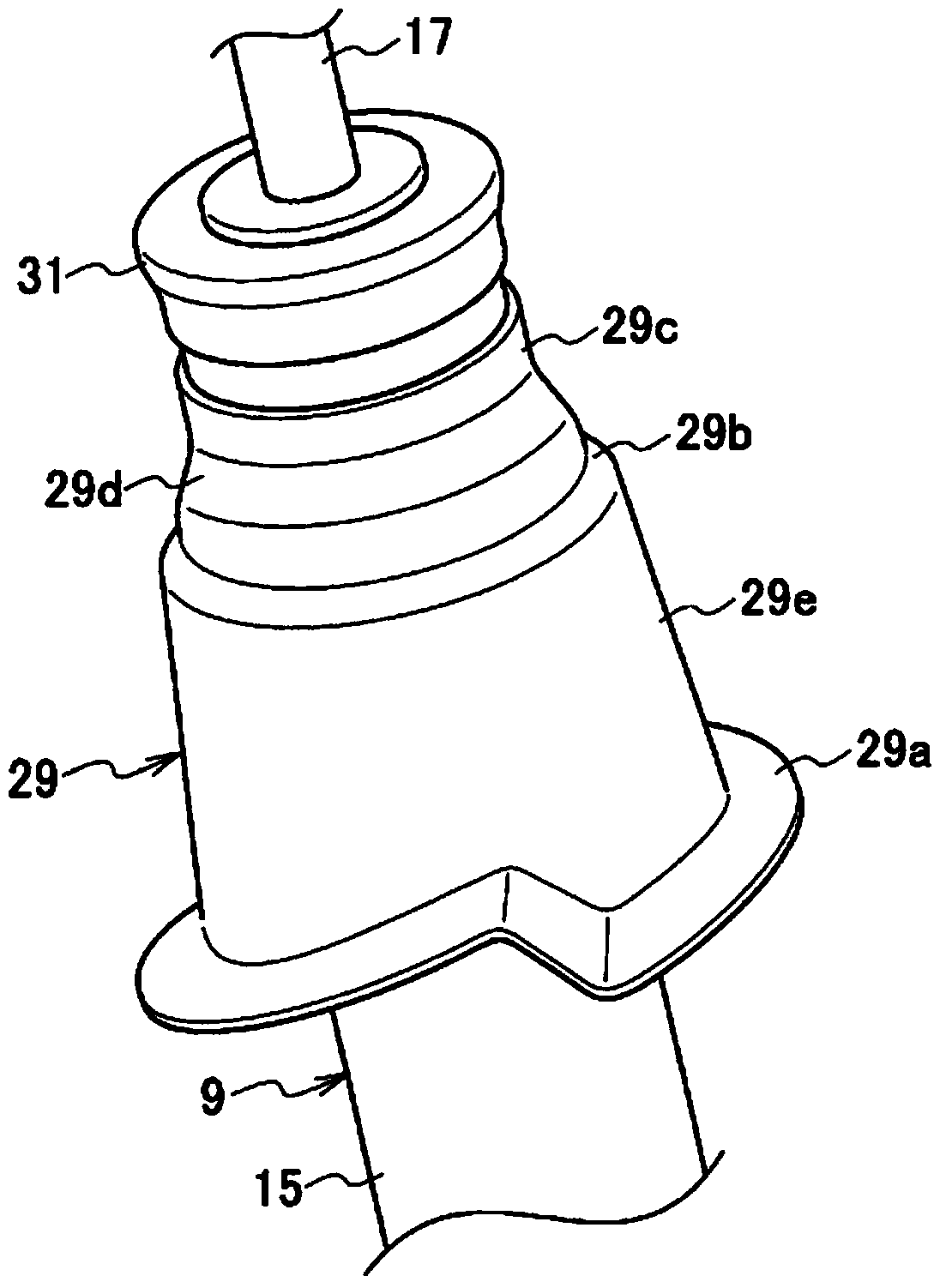
[0016] The strut damper 9 has a cylindrical case 15 arranged on the lower side, and a piston rod 17 protruding upward from the upper end of the cylindrical case 15 . The piston rod 17 is configured to be movable forward / backward with respect to the cylindrical housing 15 . In addition, the cylindrical case 15 and the piston rod 17 extend obliquely with respect to the vertical direction. Specifically, the upper p...
no. 2 Embodiment approach
[0041] The second embodiment of the present invention corresponds to making the figure 2 In the first embodiment shown, the piece portion 29a and the expansion portion 29e of the lower spring piece 29 are separate members. That is, in the second embodiment, as Figure 4 As shown, the spring movement limiting member 35 has: a mounting portion 35a mounted on the outer peripheral portion near the sealing material 31 of the cylindrical case 15 of the strut damper 9; a stepped portion 35b located at the lower portion of the mounting portion 35a, Make the bumper rubber 33 ( figure 1 ) abuts against the lower end; and the expansion part 35c, which is located at the lower part of the stepped part 35b and becomes a movement restricting part.
[0042] The inflated portion 35c constitutes a tapered portion in the same manner as the inflated portion 29c of the first embodiment, and the tapered portion is formed in a tapered shape whose inner diameter (outer diameter) gradually increase...
no. 3 Embodiment approach
[0045] The third embodiment of the present invention corresponds to the figure 2 In the first embodiment shown in , the lower spring piece 29 and the sealing material 31 are integrated. That is, the third embodiment such as Figure 5 As shown, the lower spring piece 39 integrally has the structure of the piece part 39a, the expansion part 39b, and the sealing part 39c.
[0046] The sealing portion 39c is in harmony with figure 2 The sealing material 31 is formed longer than the form extending downward, and its lower end is continuous with the stepped portion 39d, and the stepped portion 39d is in contact with the bumper rubber 33 ( figure 1 ) butt against the lower end. Therefore, here, the portion of the seal portion 39 c that faces the outer peripheral surface of the cylindrical case 15 serves as an attachment portion 39 e where the lower spring piece 39 is attached to the strut damper 9 .
[0047] As described above, according to the third embodiment, the strut damper...
PUM
 Abstract
Description
Claims
Application Information
 - R&D Engineer
- R&D Manager
- IP Professional
- Industry Leading Data Capabilities
- Powerful AI technology
- Patent DNA Extraction
Browse by: Latest US Patents, China's latest patents, Technical Efficacy Thesaurus, Application Domain, Technology Topic.
© 2024 PatSnap. All rights reserved.Legal|Privacy policy|Modern Slavery Act Transparency Statement|Sitemap