Self-cleaning type double-helical-ribbon differential velocity mixer

A double-screw belt, self-cleaning technology, applied in the direction of mixers, mixers with rotating stirring devices, mixer accessories, etc., can solve the problems of easy mixing dead angles, inability to completely replace, and lower mixing efficiency, so as to improve production Efficiency and product quality, small footprint and fast mixing times for results

Inactive Publication Date: 2014-05-07
SHANGHAI TIANYI GAODE ELECTROMECHANICAL
View PDF7 Cites 13 Cited by
  • Summary
  • Abstract
  • Description
  • Claims
  • Application Information

AI Technical Summary

Problems solved by technology

[0012] Compared with the traditional horizontal twin-ribbon mixer, the horizontal twin-shaft mixer has the above advantages, but it also has a larger footprint under the same volume, and the double-cylinder design is more likely to produce mixing dead ends. The double-shaft and double-cylinder container design Greatly increase the cost, reduce the mixing efficiency and other shortcomings, and cannot completely replace the position of the traditional horizontal double-screw ribbon mixer in the market

Method used


Image

  • Self-cleaning type double-helical-ribbon differential velocity mixer
  • Self-cleaning type double-helical-ribbon differential velocity mixer
  • Self-cleaning type double-helical-ribbon differential velocity mixer

Examples


Embodiment Construction

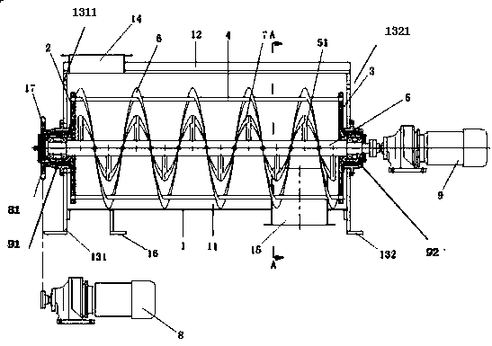
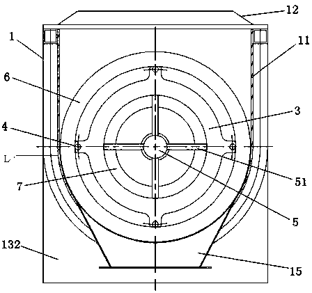
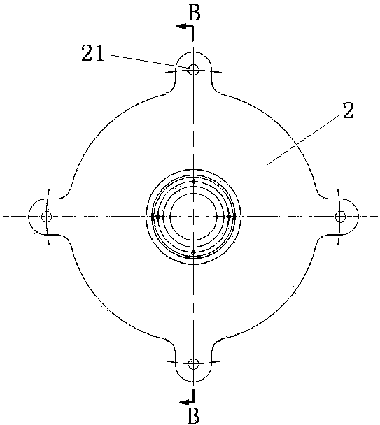
[0051] see figure 1 It is a schematic diagram of the structure of the present invention, figure 2 It is A-A sectional view of the present invention, image 3 It is a part diagram of the drive disc 2 of the present invention, Figure 4 for image 3 The B-B sectional view, Figure 5 for Figure 4 The C-C section view, Figure 6 It is part drawing and Figure 7 for Figure 6 The D-D sectional view.

[0052] Such as figure 1 As shown, a self-cleaning double-screw belt differential speed mixer includes a U-shaped casing 1, a motor-driven main shaft 5 located in the U-shaped casing 1, an inner screw belt 7 and an outer screw belt 6, wherein :

[0053] The U-shaped casing 1 is composed of a U-shaped wall 11, left and right side panels 131, 132 and a top cover 12, and a feed port 14 and a discharge port 15 are respectively arranged at two ends of the U-shaped casing 1. , the feed inlet 14 is arranged on the top cover 12, the outlet 15 is arranged at the bottom of the U-sha...


PUM


Abstract

The invention relates to a self-cleaning type double-helical-ribbon differential velocity mixer. According to the self-cleaning type double-helical-ribbon differential velocity mixer disclosed by the invention, feeding and discharge holes are formed in the two ends of a U-shaped casing respectively, a spindle is fixed on left and right side plates of the casing respectively by virtue of left and right bearing seats, inside and outside helical ribbons are driven by two motors respectively, the spindle is provided with a plurality of support rods, and the inner helical ribbon is fixed at the spindle by virtue of the support rods and is driven by the corresponding motor; the outer helical ribbon is fixed at the peripheries of a plurality of connecting rods which are connected with drive discs; the drive discs are installed at the outer rings of the left and right bearing seats and include a driving disc with mounting holes and a driven disc with mounting holes, and the mounting holes are circumferentially formed in the driving disc and the driven disc uniformly with equal quantity; one end of each connecting rod is fixed on each mounting hole of the driving disc, and the other end of each connecting rod is fixed on each mounting hole of the driven disc, so that the plurality of connecting rods are arranged on the outer side of the spindle in parallel, and the other motor drives the driving disc to enable the outer helical ribbon to rotate; the outer helical ribbon is close to the lower part of the inner wall of the U-shaped casing. With the adoption of the self-cleaning type double-helical-ribbon differential velocity mixer, when materials are mixed, the rotational directions of the inner and outer helical ribbons are opposite, and a differential velocity can be adjusted; during discharging, the rotational directions of the inner and outer helical ribbons are the same so as to increase the discharge speed.

Description

technical field [0001] The invention relates to a differential speed mixer, in particular to a self-cleaning self-cleaning double-screw belt differential speed mixer. Background technique [0002] The differential speed mixer or differential kneader is a mechanical device that uses mechanical force, shear force, etc. to uniformly mix two or more materials. During the mixing process, the moving parts of the mechanical mixer will produce a shearing effect on the material when it rotates. When the material flows through the inner wall of the container and various fixed components installed in the container, it will be sheared. These shearing effects Many local eddies are caused to spread the material evenly, increase the contact surface area of ​​the material, and accelerate the physical mixing of the material. For materials with different densities and components that are immiscible with each other, the shearing action and strong turbulence generated by the stirring will tear...

Claims


Application Information

Patent Timeline
Patent Type & Authority Applications(China)
IPC IPC(8): B01F7/08B01F15/00
Inventor 刘坚勇张衍华张凤阳曹建美
Owner SHANGHAI TIANYI GAODE ELECTROMECHANICAL
Why Eureka
Try Eureka