Novel oil cylinder clamping device

A clamping device and oil cylinder technology, which is applied in the field of new oil cylinder clamping devices, can solve the problems of increased difficulty in heat treatment, high requirements for fit clearance, and difficult processing, etc., and achieve the goals of increasing service life, stable high-speed operation, and increasing clamping force Effect

Inactive Publication Date: 2014-05-07
泉州利达机器有限公司
View PDF5 Cites 2 Cited by
  • Summary
  • Abstract
  • Description
  • Claims
  • Application Information

AI Technical Summary

Problems solved by technology

refer to figure 2 , an existing clamping method is: a fixed pipe 1' is connected behind the main shaft 2', a clamping rod 3' is provided in the inner cavity of the main shaft 2', and an oil cylinder 4' is installed behind the fixed pipe 1', and the oil cylinder 4' There is an oil cylinder shaft 5' connected with the clamping rod 3' inside, and a piston 51' is arranged on the oil cylinder shaft 5' in the oil cylinder 4', and the piston 51' on the oil cylinder shaft 5' in the oil cylinder 4' is driven by oil pressure. The clamping rod 3' makes the fixture clamp the workpiece. Since the oil cylinder 4' rotates synchronously with the main shaft 2' when the main shaft 2' is running, it is also necessary to set a stationary oil pipe joint block 41 at the free end of the oil cylinder shaft 5' ', the oil inlet hole 41' is set on the oil cylinder shaft 5', and the oil pipe joint block 42' fills the oil cylinder 4' through the oil inlet hole 41' to make the clamping device work normally, and the oil cylinder joint block 42' is required to be stationary, that is The oil cylinder joint block 42' and the oil cylinder shaft 5' rotate relatively, so the oil cylinder joint block 42' and the oil cylinder shaft 5' require wear resistance, and the difficulty of heat treatment increases; the main shaft rotates at high speed when the lathe is working, and the actual average service life of the clamping device after wear Less than one year, the service life is short, and the matching gap between the oil cylinder joint block and the oil cylinder shaft is required to be 4 μm ~ 6 μm to establish oil pressure. If the gap is greater than 6 μm, it will cause oil leakage, so the cooperation between the oil cylinder joint block and the oil cylinder shaft High clearance requirements make processing difficult

Method used


Image

  • Novel oil cylinder clamping device
  • Novel oil cylinder clamping device

Examples


Embodiment Construction

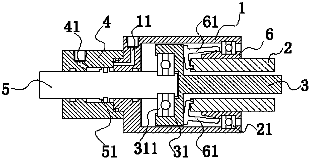
[0012] Embodiments of the present invention will be described in further detail below in conjunction with the accompanying drawings.

[0013] refer to figure 1 , a new type of oil cylinder clamping device, including a fixed pipe 1, a main shaft 2 arranged in the front of the fixed pipe 1, a clamping rod 3 arranged in the inner cavity of the main shaft 2, an oil cylinder 4 arranged at the rear end of the fixed pipe 1, an oil cylinder arranged in the oil cylinder The cylinder shaft 5 connected with the clamping rod 3 in the cylinder 4 is provided with a piston 51 on the cylinder shaft 5 in the cylinder 4, and the piston 51 divides the inner chamber of the cylinder 4 into a front chamber and a rear chamber, and between the main shaft 2 and the fixed pipe 1 A large bearing 21 is provided, and the clamping rod 3 is provided with a bearing seat 31 at one end of the inner cavity of the main shaft 2, and the bearing seat 31 is connected with the oil cylinder shaft 5 through a small b...


PUM


Abstract

The invention relates to a lathe oil cylinder clamping device and aims at providing a novel oil cylinder clamping device which does not need an oil cylinder coupling block, and is low in processing precision, low in process cost and long in service life. The novel oil cylinder clamping device comprises a fixed pipe, a main shaft arranged in the front part of the fixed pipe, a clamping pull rod arranged in the inner cavity of the main shaft, an oil cylinder arranged at the rear end of the fixed pipe and an oil cylinder shaft arranged in the oil cylinder and connected with a clamping pull rod, wherein a piston is arranged on the oil cylinder shaft in the oil cylinder to divide the inner cavity of the oil cylinder into a front cavity and a rear cavity, the main shaft is rotatably connected with the fixed pipe, one end, located in the inner cavity of the main shaft, of the clamping pull rod is rotatably connected with the oil cylinder shaft, the oil cylinder and the fixed pipe are further provided with oil inlets leading to the inner cavity of the oil cylinder, respectively, and the oil inlet formed in the oil cylinder leads to the rear cavity of the oil cylinder, while the oil inlet formed in the fixed pipe leads to the front cavity of the oil cylinder.

Description

technical field [0001] The invention relates to the technical field of lathe clamping devices, in particular to a novel oil cylinder clamping device. Background technique [0002] Machine tool processing generally installs the spindle in the spindle box, installs the fixture on the front end of the spindle, and installs the pressure device on the rear end of the spindle. The fixture fixes and clamps the workpiece through the pressure device, and then the spindle drives the workpiece to rotate at high speed for processing. refer to figure 2 , an existing clamping method is: a fixed pipe 1' is connected behind the main shaft 2', a clamping rod 3' is provided in the inner cavity of the main shaft 2', and an oil cylinder 4' is installed behind the fixed pipe 1', and the oil cylinder 4' There is an oil cylinder shaft 5' connected with the clamping rod 3' inside, and a piston 51' is arranged on the oil cylinder shaft 5' in the oil cylinder 4', and the piston 51' on the oil cylind...

Claims


Application Information

Patent Timeline
Patent Type & Authority Applications(China)
IPC IPC(8): B23Q3/12
CPCB23Q3/12
Inventor 吴聪乐颜财凭
Owner 泉州利达机器有限公司
Why Eureka
Try Eureka