Centrifugal fan blade structure

A fan blade and tangent technology, applied in the field of centrifugal fan blade structure, can solve problems such as high noise, inability to characterize, and limited structural design

Inactive Publication Date: 2014-05-07
ASIA VITAL COMPONENTS SHENZHEN CO LTD
View PDF4 Cites 1 Cited by
  • Summary
  • Abstract
  • Description
  • Claims
  • Application Information

AI Technical Summary

Problems solved by technology

[0004] 1. Structural design is limited;
[0005] 2. Unable to fle

Method used


Image

  • Centrifugal fan blade structure
  • Centrifugal fan blade structure
  • Centrifugal fan blade structure

Examples


Embodiment Construction

[0035] The above-mentioned purpose of the present invention and its structural and functional characteristics will be described according to the preferred embodiments of the accompanying drawings.

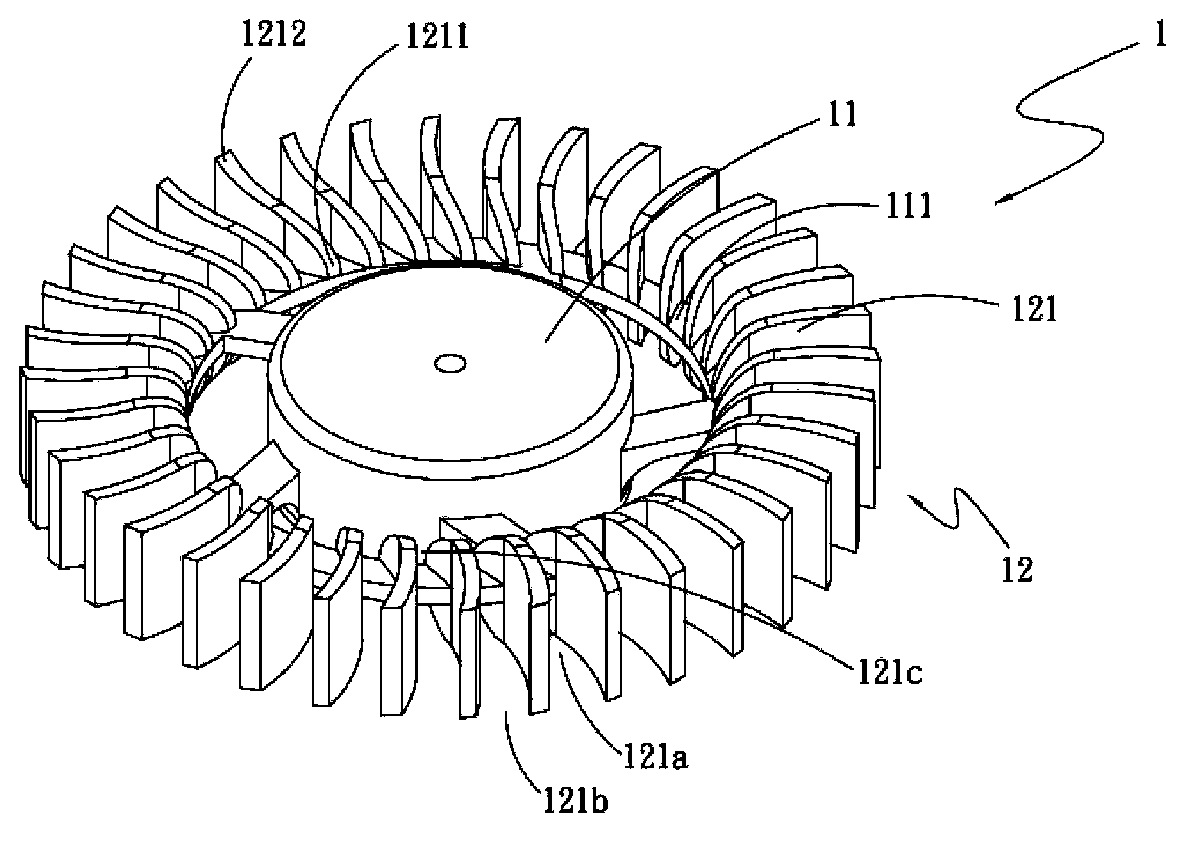
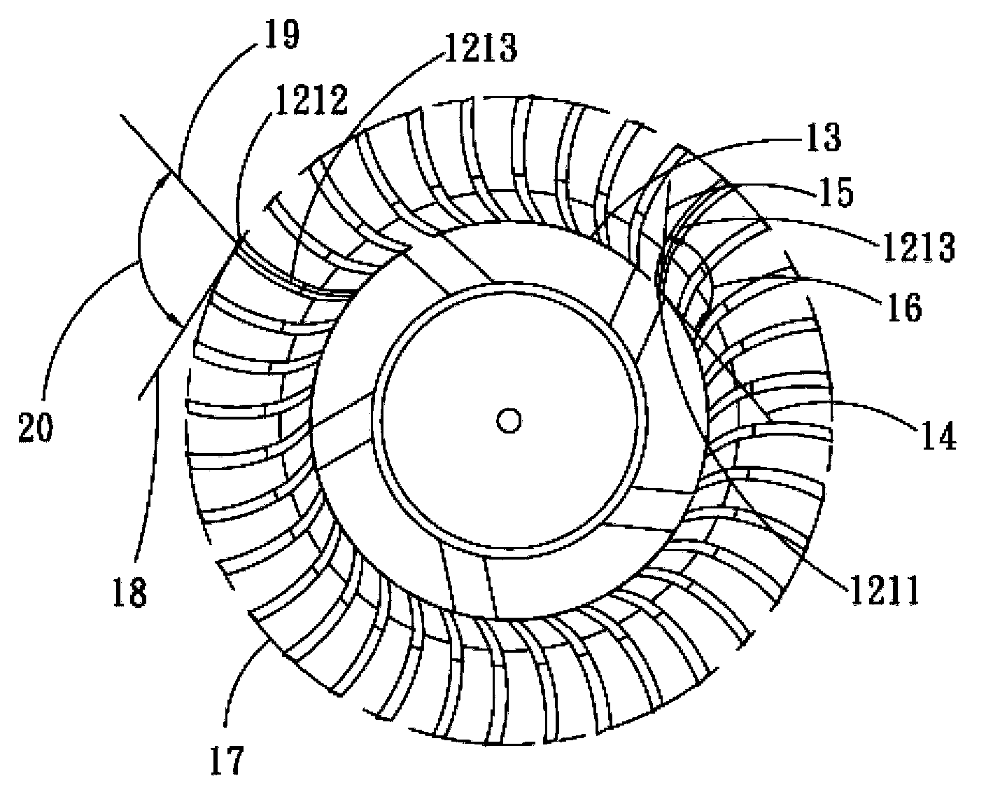
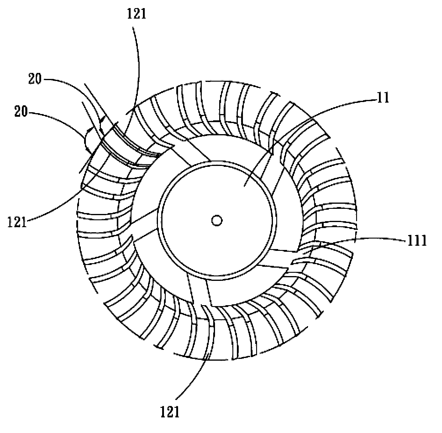
[0036] see figure 1 , figure 2 , is a three-dimensional and top view of the first embodiment of the centrifugal blade structure of the present invention, as shown in the figure, the centrifugal blade structure 1 includes: a hub 11, a blade body group 12;

[0037] The hub 11 has an extension 111;

[0038] The fan blade group 12 has a plurality of fan blade bodies 121, the fan blade body 121 is configured by extending outward from the extension portion 111, and the fan blade body 121 has a flow channel 121a and an air outlet 121b and An air inlet 121c, the air outlet 121b and the air inlet 121c are respectively arranged at two ends of the flow channel 121a and communicated with the flow channel 121a, and the air outlets 121b are not equidistantly arranged.

[0039] The blade body...


PUM


Abstract

A centrifugal fan blade structure comprises a hub and a fan blade body group. The hub is provided with an extension portion, and the fan blade body group comprises a plurality of fan blade bodies which extend outwards from the extension portion. A flow passage, an air outlet and an air inlet are formed between every two fan blade bodies. The air outlets and the air inlets are formed in the two ends of the flow passages and communicated with the flow passages. The air outlets are arranged in a non-equidistant mode, and accordingly, operation noise can be greatly reduced.

Description

technical field [0001] A centrifugal fan blade structure, especially a centrifugal fan blade structure that can reduce the noise of a centrifugal fan during operation. Background technique [0002] With the rapid development of the current electronic industry, the performance of electronic components continues to improve. As the calculation speed increases, the heat generated by it will generate relatively large amounts of heat. If the heat cannot be dissipated immediately, the computing performance of the electronic components will decrease. If it is serious, it will cause burning. Therefore, in a limited system space, a small centrifugal fan is used as a heat solution. The centrifugal fan mainly includes a frame, a fan hub, and multiple rings arranged outside the fan hub. Each fan blade body has an air inlet on the top and bottom of the frame body, and an air outlet on its side. When it is running, the fan blade body rotates to drive the surrounding air to flow, and the sh...

Claims


Application Information

Patent Timeline
IPC IPC(8): F04D29/28
Inventor 杨志伟李生丕
Owner ASIA VITAL COMPONENTS SHENZHEN CO LTD
Why Eureka
Try Eureka