Positioning and locking device for ball valve

A technology for positioning and locking ball valves, applied to valve devices, devices to prevent accidental or unauthorized actions, cocks including cut-off devices, etc., can solve the problem of internal leakage of ball valves, changing ball valves by touching, and affecting the position accuracy of ball valves and other issues to achieve the effect of wide adaptability

Active Publication Date: 2014-05-07
ZHANGJIAGANG FURUI SPECIAL EQUIP CO LTD
View PDF8 Cites 8 Cited by
  • Summary
  • Abstract
  • Description
  • Claims
  • Application Information

AI Technical Summary

Problems solved by technology

[0002] At present, the traditional limit device of the ball valve is to weld the limit stop post on the bonnet, and there is no locking device after the limit, and the handle is installed on the valve stem. If the limit is set, the limit column is easy to loosen and fall off afte

Method used


Image

  • Positioning and locking device for ball valve
  • Positioning and locking device for ball valve

Examples


Embodiment Construction

[0015] The present invention will be further described in detail below through specific embodiments.

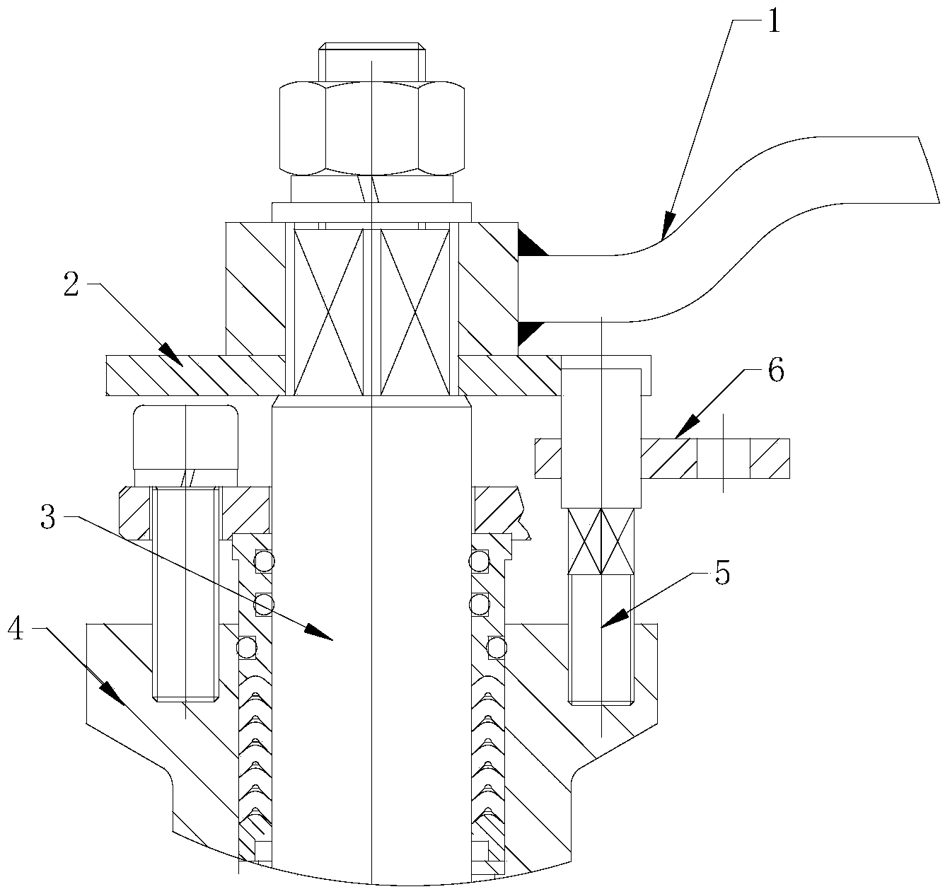
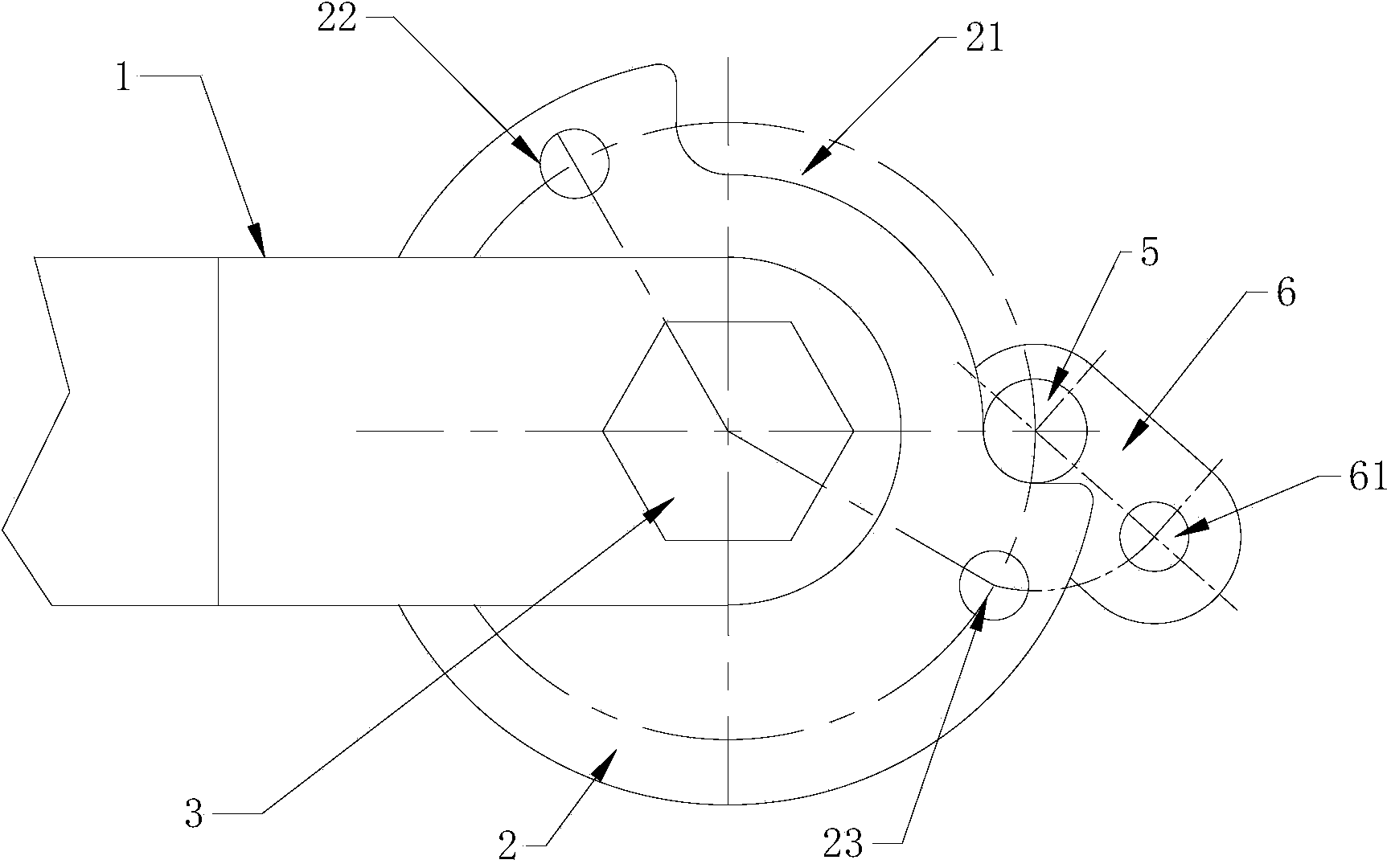
[0016] Such as figure 1 , 2 As shown, a positioning and locking device for a ball valve includes a limit post 5 fixed on the valve cover 4; a limit disc 2 fixed on the valve stem 3, and a limit gap 21 or limit is provided on the limit disc 2 In this embodiment, the limit disc 2 is provided with a limit gap 21, the limit post 5 is located in the limit gap 21, if it is replaced with a limit slot, then the limit post 5 is constrained to the limit slot Inside; the limit post 5 is rotatably installed with a locking block 6; the height of the upper end surface of the locking block 6 is lower than the lower end surface of the limit disc 2, and the locking block 6 is provided with a movable locking hole 61, The limit disk 2 is provided with a static locking hole that is matched with a locking fixing hole, and the dynamic locking hole 61 is matched with the static locking hole and can be...


PUM


Abstract

The invention discloses a positioning and locking device for a ball valve. The positioning and locking device comprises a limiting post fixed to a valve cover and a limiting disk fixed to a valve rod, wherein the limiting disk is provided with a limiting gap or a limiting groove; the limiting post is positioned in the limiting gap or the limiting groove; a locking block is rotationally arranged on the limiting post; the upper end face of the locking block is lower than the lower end face of the limiting disk; the locking block is provided with a dynamic locking hole; the limiting disk is provided with a static locking hole matched with the locking fixing hole; the dynamic locking hole and the static locking hole are matched with each other, and can be locked through a locking piece. By adopting the positioning and locking device, the opening or closing state of the ball valve can be positioned, and the ball valve can be locked, so that the accuracy of the ball valve is ensured, and internal leakage is avoided.

Description

Technical field [0001] The invention relates to a positioning and locking device, in particular to a positioning and locking device of a ball valve. Background technique [0002] At present, the traditional limit device of the ball valve is to weld the limit stop post on the valve cover, and there is no locking device after the limit, and the handle is installed on the valve stem. When the handle rotates, one end of the handle abuts on the limit block. In this way, the limit post is easy to loosen and fall off after repeated operations, and in the absence of a position locking device, the handle is likely to be touched inadvertently to change the switch position of the ball valve, which affects the accuracy of the switch position of the ball valve. It is easy to cause internal leakage of the ball valve. Summary of the invention [0003] The technical problem to be solved by the present invention is to provide a positioning and locking device for a ball valve, which can position t...

Claims


Application Information

Patent Timeline
IPC IPC(8): F16K35/06F16K5/06
CPCF16K5/06F16K35/10
Inventor 伍国东胡晨曦王瑞东周晓会张宏豫陆嘉君
Owner ZHANGJIAGANG FURUI SPECIAL EQUIP CO LTD
Why Eureka
Try Eureka