

Textile air pipe
A technology for textile air ducts and air intake ducts is applied in the field of ventilation ducts, which can solve the problems of easy air turbulence, simple structure of air ducts, jittering of exhaust ducts, etc., and achieves good air induction effect, good filtering effect, and avoidance of jitter. Effect
- Summary
- Abstract
- Description
- Claims
- Application Information
AI Technical Summary
Problems solved by technology
Method used
Image

Examples
Embodiment
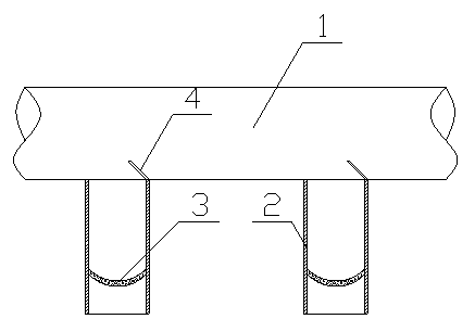
[0010] Embodiment: as a kind of implementation mode of the present invention, as figure 1 As shown, a textile air duct includes an air inlet pipe 1, and several exhaust pipes 2 are vertically arranged on the air inlet pipe 1, and the number of the exhaust pipes 2 is two or more. 2 An air deflector 4 is provided at the air inlet to guide the air flow into the exhaust pipe 2. The angle between the air deflector 4 and the air inlet pipe 1 is 45°, and the air induction effect is good. The exhaust pipe 2 is equipped with There is a grid plate 3, and the air outlet holes are uniformly opened on the grid plate 3, which can filter the turbulent airflow into an advection, and avoid the vibration of the exhaust pipe 2. The grid plate 3 is curved, with a large contact area, and the filtering effect it is good.
PUM
 Abstract
Description
Claims
Application Information