Constant-torque mechanism for clock, movement having the mechanism, and mechanical clock

A constant torque and clock technology, applied in the field of constant torque mechanism, can solve problems such as inability to be directly applicable

Inactive Publication Date: 2014-05-07
SEIKO INSTR INC
View PDF2 Cites 14 Cited by
  • Summary
  • Abstract
  • Description
  • Claims
  • Application Information

AI Technical Summary

Problems solved by technology

[0012] However, if this structure is directly applied to the power source of the watch, the two reels will rotate together with the winding, so whenever the spring is tightened, it needs to be removed from the wheel train for moving the needle, so it cannot be directly applied.

Method used


Image

  • Constant-torque mechanism for clock, movement having the mechanism, and mechanical clock
  • Constant-torque mechanism for clock, movement having the mechanism, and mechanical clock
  • Constant-torque mechanism for clock, movement having the mechanism, and mechanical clock

Examples


Embodiment

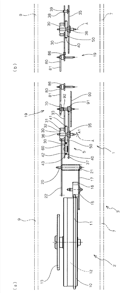
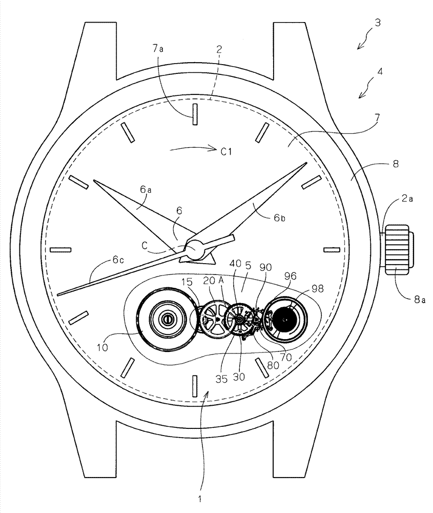
[0050] exist Figure 1 to Figure 3 In the figure, a constant torque mechanism 1 for a timepiece according to a preferred embodiment of the present invention, a movement 2 according to a preferred embodiment of the present invention equipped with the mechanism 1, and a mechanical timepiece according to a preferred embodiment of the present invention are shown. 3.

[0051] The mechanical clock 3 has such figure 1 Appearance 4 as shown. That is, the timepiece 3 includes a time display hand 6 composed of an hour hand 6 a , a minute hand 6 b , and a second hand 6 c rotatable about the central axis C in the clockwise direction C1 . The dial 7 of the timepiece 3 has engraved characters 7a indicating the position of the hour. 8 is a watch case.

[0052] Apart from figure 1 Besides, from image 3 It can be seen from the cross-sectional explanatory diagrams of (a) and (b) that the movement 2 is accommodated in the packaging parts of the mechanical timepiece 3, that is, behind th...


PUM


Abstract

The present invention relates to and provides a constant-torque mechanism for a clock, a movement having the mechanism, and the mechanical clock, which are capable of suppressing the output torque fluctuations to a minimum level. The constant torque mechanism of the movement of the mechanical clock is disposed between a barrel wheel and a balance wheel and comprises: a first reel; a second reel which is eccentric relative to the axis; a detaching wheel which comprises a ratchet and is combined with a drive wheel and capable of rotating around the central axis of the first reel; the drive wheel which is combined with a driven side wheel column and capable of rotating around the central axis with respect to the detaching wheel; a strip which is in a form of an elastic tape member and winding between the first reel and the second reel for forming the constant-torque mechanism, wherein the first reel is mounted on one of the detaching wheel and the drive wheel and the second reel is mounted on the other one of the detaching wheel and the drive wheel; and an intermittent rotation control mechanism which allows the detaching wheel to rotate with respect to the drive wheel in an intermittent mode..

Description

technical field [0001] The present invention relates to a constant torque mechanism for a timepiece, a movement having the same, and a mechanical timepiece. Background technique [0002] In mechanical timepieces, in order to avoid fluctuations in the torque transmitted from the barrel to the balance via the escape wheel depending on the degree of unwinding of the mainspring of the barrel, it is known that the torque is transferred from the barrel to the balance. A constant force (Remontoire) mechanism is set between the fourth wheel of the energy transmission path and the escape wheel. [0003] Such as Figure 7 as well as Figure 8 As shown, the movement 102 of the timepiece 103 equipped with the constant force mechanism 200 has a barrel wheel 110, a second wheel 120, a third wheel 130, a constant force mechanism 200, an escape wheel 140, a pallet fork (anchor) 150 and a balance Wheel 160. The constant force mechanism 200 includes a pull-in wheel (roll-in wheel) 210 , a ...

Claims


Application Information

Patent Timeline
Patent Type & Authority Applications(China)
IPC IPC(8): G04B15/14
CPCG04B1/22G04B1/225
Inventor 藤枝久
Owner SEIKO INSTR INC
Why Eureka
Try Eureka