High-brightness dimmable COB light source, spot lamp COB process and fluorescent lamp COB process

A high-brightness, dimming technology, applied in the direction of electrical components, electrical solid-state devices, circuits, etc., can solve the problems of high production cost, unsuitable for large-area products, high cost of material base, etc., and achieve low production difficulty, simple structure, The effect of promoting the use of

Active Publication Date: 2014-05-07
SHENZHEN HUATIAN MAIKE OPTOELECTRONICS TECH CO LTD
View PDF4 Cites 6 Cited by
  • Summary
  • Abstract
  • Description
  • Claims
  • Application Information

AI Technical Summary

Problems solved by technology

[0002] Among the existing technologies, the ceramic COB light source technology is widely used. This technology has the advantages of high thermal conductivity and high light efficiency, but the disadvantage of this technology is that the cost of the material base is high, and it is not suitable for large-area products.
Moreover, in the prior art, the structure of the high-brightness COB light source and the dimmable COB light source are relatively complicated, and the production process is also very complicated, resulting in high production costs of this type of COB light source.
In addition, there is no high-brightness and dimmable COB light source in the existing market

Method used


Image

  • High-brightness dimmable COB light source, spot lamp COB process and fluorescent lamp COB process
  • High-brightness dimmable COB light source, spot lamp COB process and fluorescent lamp COB process
  • High-brightness dimmable COB light source, spot lamp COB process and fluorescent lamp COB process

Examples


no. 1 example

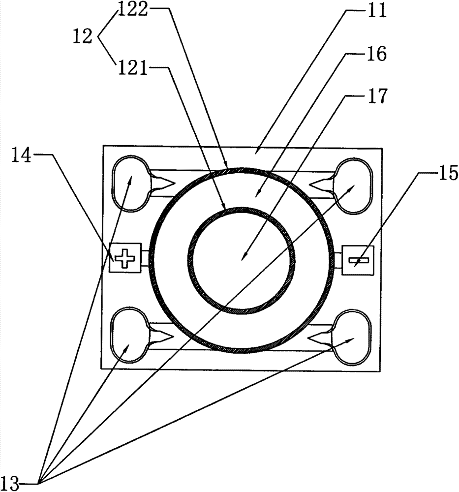
[0046] The first embodiment, in this embodiment, the barrier wall 12 divides the substrate 11 into a first light-emitting area 16 and a second light-emitting area 17; the first light-emitting area 16 is circular, the second light-emitting area 17 is circular, and the second The light emitting area 17 is located in the inner circle of the annular first light emitting area 16 ; the barrier wall 12 is located between the first light emitting area 16 and the second light emitting area 17 . The retaining wall 12 includes a first retaining wall 12 and a second retaining wall 122 ; the first retaining wall 12 is located between the first light-emitting area 16 and the second light-emitting area 17 , and the second retaining wall 122 is located on the periphery of the first light-emitting area 16 . The LED chips in the first light emitting area 16 are positive white LEDs, and the LED chips in the second light emitting area 17 are warm white LEDs.

[0047] The first embodiment is a hig...

no. 2 example

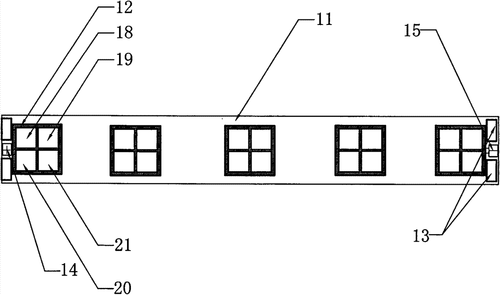
[0048]The second embodiment, in this embodiment, the barrier wall 12 divides the substrate 11 into the third light emitting area 18, the fourth light emitting area 19, the fifth light emitting area 20 and the sixth light emitting area 21; the third light emitting area 18, the sixth light emitting area The four light-emitting regions 19, the fifth light-emitting region 20 and the sixth light-emitting region 21 are joined together to form a rectangle; the colors of light emitted by the four light-emitting regions are not completely the same.

[0049] The second embodiment is a high-brightness two-color dimmable COB fluorescent lamp. The fluorescent lamp includes four light-emitting areas arranged in a square grid, and the four light-emitting areas are joined together to form a rectangle. Moreover, the colors of light emitted by the four light-emitting areas are not completely the same, and can be two-color or three-color. In the case of two colors, the LED chips in the third lum...


PUM


Abstract

The invention discloses a high-brightness dimmable COB light source. The high-brightness dimmable COB light source comprises a plurality of bonding pads used for reinforcement, a plurality of LED chips with different light colors, a substrate, a retaining wall, a positive electrode and a negative electrode, wherein the retaining wall is fixed on the substrate, and the retaining wall divides the substrate into a plurality of light emitting areas; the LED chip with different light colors are fixed in different light emitting areas respectively; the LED chips located in different light emitting areas are electrically connected with the positive electrode and the negative electrode independently; the retaining wall is a transparent; and the bonding pads are uniformly distributed on the substrate. The high-brightness dimmable COB light source provided by the utility model is provided with a plurality of light emitting areas, two adjacent light emitting areas are isolated by transparent box dam glue, thereby enabling light emitted by each of the light emitting areas to penetrate through the retaining wall and transmit to one or more adjacent light emitting areas. Each of the light emitting areas can adjust current independently, thereby realizing a function of controlling the color temperature and the brightness of each of the light emitting areas independently.

Description

technical field [0001] The invention relates to the field of COB light sources, in particular to a high-brightness dimmable COB light source, a spotlight COB process, and a fluorescent lamp COB process. Background technique [0002] Among the existing technologies, the ceramic COB light source technology is widely used. This technology has the advantages of high thermal conductivity and high light efficiency, but the disadvantage of this technology is that the cost of the material base is high, and it is not suitable for large-area products. Moreover, in the prior art, the structure of the high-brightness COB light source and the dimmable COB light source are relatively complicated, and the production process is also very complicated, resulting in a high production cost of this type of COB light source. In addition, there is no high-brightness and dimmable COB light source in the existing market. Contents of the invention [0003] Aiming at the deficiencies in the above t...

Claims


Application Information

Patent Timeline
Patent Type & Authority Applications(China)
IPC IPC(8): H01L25/13H01L33/48H01L33/62
Inventor 陈苏南
Owner SHENZHEN HUATIAN MAIKE OPTOELECTRONICS TECH CO LTD
Why Eureka
Try Eureka