In-situ cutting conveyer and positioning conveying method
A conveyor and conveying mechanism technology, applied in the direction of sending objects, transportation and packaging, metal processing, etc., can solve the problems of test strip flipping and inaccurate positioning, and achieve the effect of improving work efficiency
- Summary
- Abstract
- Description
- Claims
- Application Information
AI Technical Summary
Problems solved by technology
Method used
Image

Examples
Embodiment 1
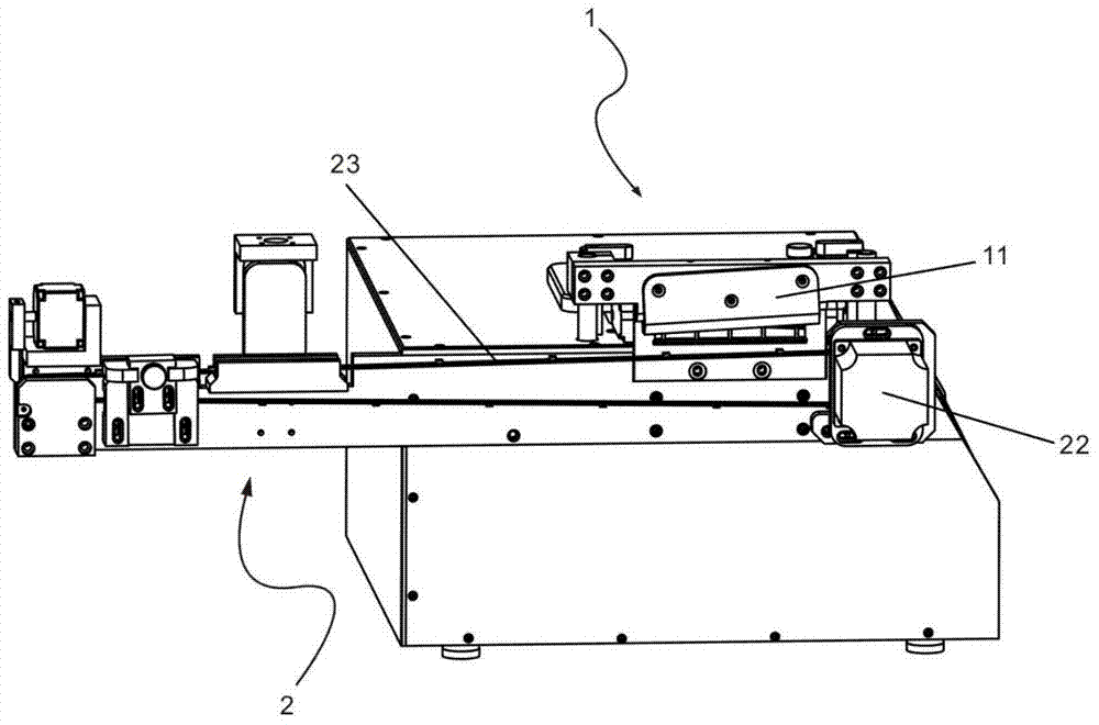
[0070] Refer below figure 1 An in-situ chop conveyor of one embodiment of the invention is described.
[0071] Such as figure 1 As shown, the in-situ chopping conveyor includes a chopping mechanism 1, that is, a part of the existing paper cutter body, and the chopping mechanism 1 includes a first driving device (not shown in the figure) and a chopping device 11 ; In this embodiment, the chopping device 11 includes an upper knife, and the first driving device can drive the upper knife to reciprocate up and down, so as to realize the chopping of the material to be cut, that is, embodiment 1 realizes cutting in the manner of chopping Process materials.
[0072] Depend on figure 1 , the in-situ chopping conveyor also includes a first conveying mechanism 2, which includes a second driving device 22 and a first conveying device 23, the second driving device 22 can drive the first conveying device 23 for directional conveying, and the first conveying The device 23 is located b...
Embodiment 2
[0087] The essence of embodiment 2 is a different implementation of the cutting mechanism. Compared with the cutting method provided in embodiment 1, embodiment 2 cuts the material in the way of rolling cutting / sliding cutting.
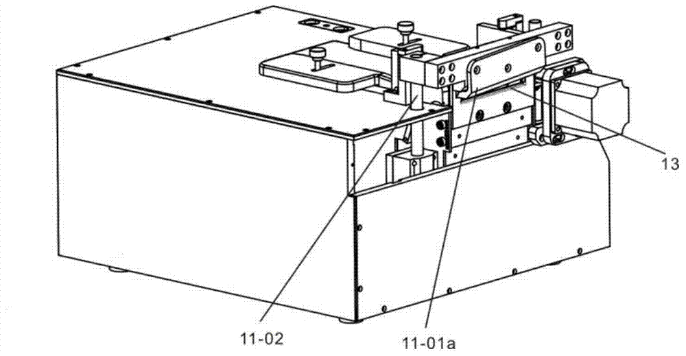
[0088] Such as Figure 7 As shown, the chopping mechanism is still provided with two limit blocks on the left and right to limit the material to be cut, and the upper knife 11-01 is arranged on the slide bar 11-03, and the upper knife 11-01 can be driven by the first driving device. It reciprocates left and right on the slide bar under the driving action of the driving force.
[0089] Such as Figure 7 As shown, the upper knife 11-01 has a compacting part 11-01a. Preferably, one side of the compacting part 11-01a can compact the material to be cut, and the other side can compact the rolled-cut material. Specifically: the inscribed surface of the upper knife 11-01 fits the lower edge of the material outlet 13, and the conveying surface of the first c...
Embodiment 3
[0091] The essence of embodiment 3 is a different implementation of the first conveying mechanism. Compared with the conveying mode of the first conveyor belt provided in embodiment 1, embodiment 3 cuts the material by sliding / rolling the conveying plate .
[0092] Such as Figure 8 as shown, Figure 8 Only different implementations of the first conveying mechanism in this embodiment are given, and other mechanisms are the same as those provided in Embodiment 1 and their principles.
[0093] see Figure 8 , the first conveying device includes a rail 23-1 and a slider 23-2, in this embodiment, the slider 23-2 cooperates with the rail 23-1, and under the action of the second driving device 22, It can reciprocate along the track 23-1, and the slider 23-2 is provided with a conveying surface 23-2a, and the chopped material is compacted and placed on the conveying surface 23-2a, and then the chopped material is passed through the slider 23-2. Oriented delivery of materials.
...
PUM
 Abstract
Description
Claims
Application Information
 - R&D Engineer
- R&D Manager
- IP Professional
- Industry Leading Data Capabilities
- Powerful AI technology
- Patent DNA Extraction
Browse by: Latest US Patents, China's latest patents, Technical Efficacy Thesaurus, Application Domain, Technology Topic.
© 2024 PatSnap. All rights reserved.Legal|Privacy policy|Modern Slavery Act Transparency Statement|Sitemap