Surge pressure control short joint

A pressure-activating and sub-joint technology, applied in the direction of drill pipe, casing, drill pipe, etc., can solve problems such as increased operating time and cost, drill sticking, formation fracture, etc.

Active Publication Date: 2014-05-14
CNOOC ENERGY TECH & SERVICES
View PDF8 Cites 2 Cited by
  • Summary
  • Abstract
  • Description
  • Claims
  • Application Information

AI Technical Summary

Problems solved by technology

[0002] At present, in offshore oilfield drilling operations, due to the influence of water depth, there is an objective fact that the window between formation pressure equivalent density and fracture pressure equivalent density is narrow in deep water drilling operations. As the water depth increases, the window value continues to decrease. Small pressure fluctuations will bring the risk of formation rupture and collapse at the bottom of the well. Therefore, once the running speed is too fast when running the casing, liner and other pipe strings, it is very easy to cause formation rupture, collapse, and even leakage. , and the frequency of leakage is also higher
At present, the operation risk is mainly reduced by controlling the speed of the lower pipe string, but at the same time, controlling the speed of the lower pipe string will bring operational risks such as obstruction or stuck pipe, and increase the operation time and cost

Method used


Image

  • Surge pressure control short joint
  • Surge pressure control short joint
  • Surge pressure control short joint

Examples


Embodiment Construction

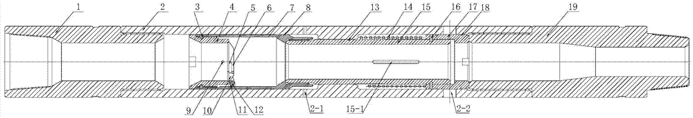
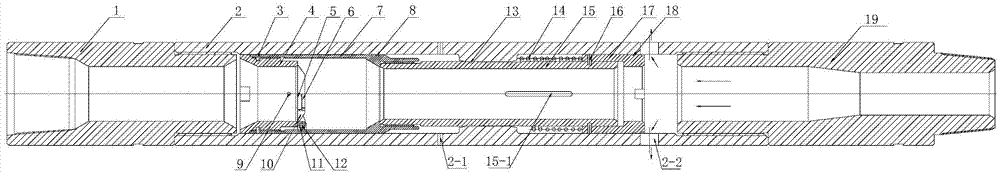
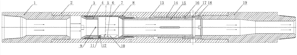
[0027] In order to further understand the invention content, characteristics and effects of the present invention, the following examples are given, and detailed descriptions are as follows in conjunction with the accompanying drawings:

[0028] see figure 1 , the activation pressure control pup joint, including the tool connection mechanism, the middle pup joint 2 and the internal pressure relief mechanism, the tool connection mechanism includes the upper joint 1 connected with the upper tool and the lower joint 19 connected with the lower tool, the middle short The joints are respectively connected with the upper joint and the lower joint of the tool connection mechanism, and the upper part of the lower joint is formed with a limit step that can realize the downward limit of the internal pressure relief mechanism. An internal pressure relief mechanism is installed in the middle nipple, and the internal pressure relief mechanism includes a valve seat 4, a valve seat sleeve 7,...


PUM


Abstract

The invention relates to a surge pressure control short joint which comprises a tool connecting mechanism, a middle short joint body and an internal pressure releasing mechanism. The middle short joint body is respectively connected with an upper connector of the tool connecting mechanism and a lower connector of the tool connecting mechanism. The surge pressure control short joint is characterized in that the internal pressure releasing mechanism is installed in the middle short joint body and comprises a valve seat, a valve seat sleeve, a valve plate, a torsional spring, a spring, a connecting shaft and a movable sleeve, the valve seat is connected with the valve seat sleeve, the other end of the valve seat sleeve is connected with the connecting shaft, the connecting shaft is sleeved with the spring, the other end of the connecting shaft and the movable sleeve are fixed, the valve plate is installed on one end face of the valve seat, a spraying nozzle is formed in the lateral side of the valve seat, a valve seat sealing ring is installed on the valve seat sleeve, and a bypass sealing ring is arranged on the movable sleeve. The surge pressure control short joint has the advantages that well leakage risks caused by the surge pressure can be reduced when a sleeve is installed; the surge pressure control short joint can be used for controlling the underground surge pressure in tail tube installation operation and other kinds of underground tubular column operation to reduce stratum fracturing and loss risks; the tubular column installation speed is quickened, and the efficiency for installing a tail tube and other tubular columns under a deep well and a convention well with complex geological conditions is greatly improved.

Description

technical field [0001] The invention belongs to the technical field of oil and gas drilling, and in particular relates to an excited pressure control sub-joint capable of reducing the risk of lost circulation caused by excited pressure when casing is run. Background technique [0002] At present, in offshore oilfield drilling operations, due to the influence of water depth, there is an objective fact that the window between formation pressure equivalent density and fracture pressure equivalent density is narrow in deep water drilling operations. As the water depth increases, the window value continues to decrease. Small pressure fluctuations will bring the risk of formation rupture and collapse at the bottom of the well. Therefore, once the running speed is too fast when running the casing, liner and other pipe strings, it is very easy to cause formation rupture, collapse, and even leakage. , and the frequency of leakage is also higher. At present, the operation risk is mai...

Claims


Application Information

Patent Timeline
Patent Type & Authority Applications(China)
IPC IPC(8): E21B17/02
Inventor 马认琦刘景超赵维青刘传刚郑伟陈杰关清涛
Owner CNOOC ENERGY TECH & SERVICES
Why Eureka
Try Eureka