Rubber frame, backlight module and display device

A technology of backlight module and display device, applied in the field of plastic frame, backlight module and display device, to achieve the effect of avoiding damage

Inactive Publication Date: 2014-05-14
CHENGDU BOE OPTOELECTRONICS TECH CO LTD +1
View PDF5 Cites 5 Cited by
  • Summary
  • Abstract
  • Description
  • Claims
  • Application Information

AI Technical Summary

Problems solved by technology

[0006] The purpose of the present invention is to solve the problem in the prior art that the corner of the display panel where the plastic frame is fitted is prone to stress with the hard plastic frame, and to provide a plastic frame that can undergo elastic deformation

Method used


Image

  • Rubber frame, backlight module and display device
  • Rubber frame, backlight module and display device
  • Rubber frame, backlight module and display device

Examples


Embodiment 1

[0035] Such as Figure 4-8 As shown, this embodiment provides a plastic frame and a backlight assembly including the plastic frame, wherein the plastic frame 1 includes a frame 4 for fixing the display panel and an elastically deformable stopper located at the connection between two adjacent sides of the frame 4 wall3.

[0036] It should be understood that, according to the different distribution positions of the backlight in the LCD, the backlight can be divided into two types: edge-lit backlight and direct-lit backlight, wherein the edge-lit backlight is placed on the side of the LCD display panel. , The direct-type backlight is placed under the LCD display panel. In Embodiment 1, the backlight module of an edge-lit backlight is introduced as an example. The backlight module usually includes various layers of film materials, adhesive tapes, light guide plates, light sources and other backlight components, so details will not be repeated here.

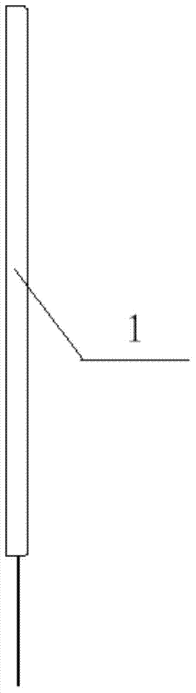
[0037] The frame 4 of the pl...

Embodiment 2

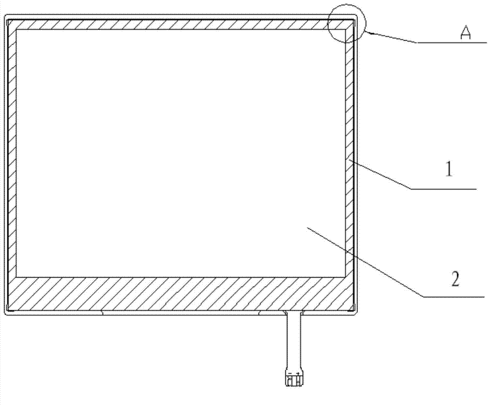
[0051] This embodiment provides a display device, which includes a display panel and the above-mentioned backlight module, and the display panel is assembled in a plastic frame of the backlight module.

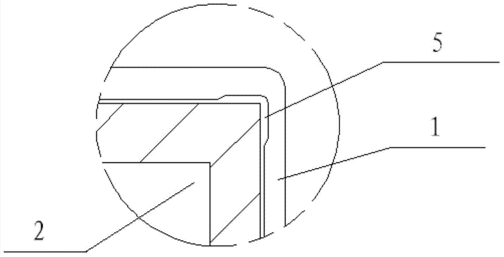
[0052] Figure 7 It is a schematic structural diagram of a backlight module of a display device embedded in a display panel. Such as Figure 7 As shown, the display panel 2 is protected by retaining walls 3 at four corners. Figure 8 for Figure 7 In the enlarged schematic diagram of part C in the middle, the distance d between the retaining wall 3 and the display panel 2 is 0.1-0.15mm, so that an appropriate buffer distance is set between the retaining wall 3 and the display panel 2, more It is beneficial for the retaining wall 3 to play a protective function.

[0053] Preferably, the distance between the retaining wall 3 of the plastic frame 1 and the display panel is 0.1-0.15mm.

[0054] When the surroundings of the display device of the present invention are subjected...


PUM


Abstract

The invention provides a rubber frame, backlight module and display device, and belongs to the display technical field. The problem that stress can be generated easily in corners of a display panel which is embedded by the rubber frame, backlight module and display device and a hard rubber frame in an existing design can be solved. The rubber frame, backlight module and display device comprise a frame which is made of hard materials and retaining walls which are made of soft materials. The frame has a supporting, positioning and protecting function on various backlight modules. Meanwhile, the display panel is embedded, and damage to all functional layers due to collision, extrusion and the like is avoided. The retaining walls correspond to the corners of the display panel, key protection of the corner parts of the liquid crystal display panel can be achieved, and damage to the liquid crystal display panel is prevented due to the fact that the display panel makes contact with the hard rubber part when being subjected to external force.

Description

technical field [0001] The invention belongs to the field of display technology, and in particular relates to a plastic frame, a backlight module and a display device. Background technique [0002] Liquid crystal display devices have the advantages of lightness, thinness, and low power consumption, and are widely used in modern information equipment. Since liquid crystal displays (Liquid Crystal Display Device, LCD for short) do not have light-emitting characteristics, they need to rely on backlight sources to supply sufficient and evenly distributed light sources. To achieve the display function, so the performance of the backlight module directly affects the quality of the LCD. With the development of liquid crystal display devices towards narrow bezels, the backlight module must not only meet the appearance requirements of narrow bezels while providing light sources, but also effectively protect the LCD. The four corners of the LCD are most easily placed Damage occurs un...

Claims


Application Information

Patent Timeline
Patent Type & Authority Applications(China)
IPC IPC(8): F21V21/00F21S8/00G02F1/13357
CPCG02F1/133308G02F1/133608G02F2201/503G02F1/133317A47B81/06H05K5/0017
Inventor 陈佳
Owner CHENGDU BOE OPTOELECTRONICS TECH CO LTD
Why Eureka
Try Eureka