Aero-engine rotor air floatation assembling method and device based on inductance measurement
An aero-engine, inductance measurement technology, applied in the field of mechanical assembly, can solve problems such as low coaxiality, and achieve the effects of reducing noise pollution, reducing vibration, and saving fuel consumption
- Summary
- Abstract
- Description
- Claims
- Application Information
AI Technical Summary
Problems solved by technology
Method used
Image

Examples
Embodiment Construction
[0020] Below in conjunction with accompanying drawing, the present invention is described in further detail:
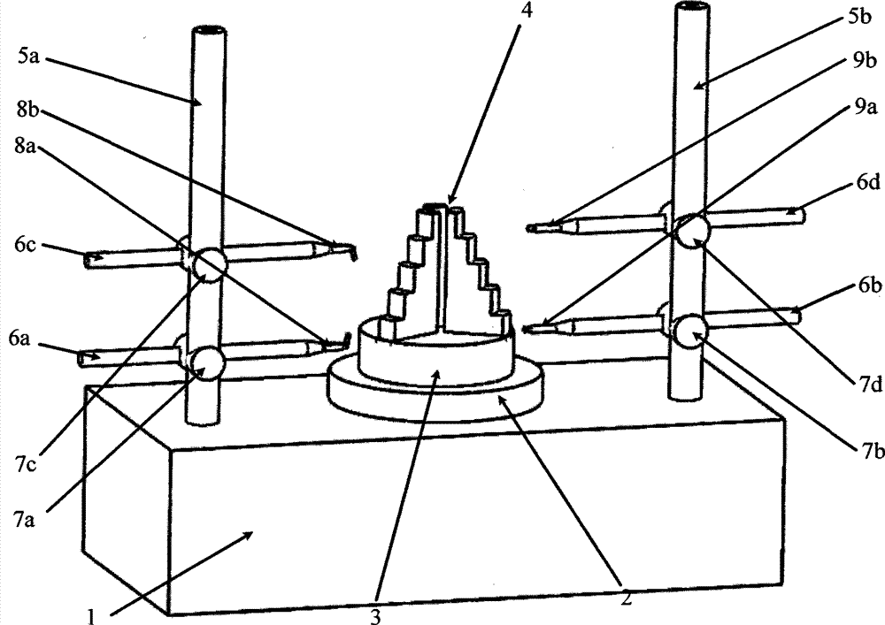
[0021] An air-floating assembly method and device for an aero-engine rotor based on inductance measurement, the method and device are as follows: a three-jaw hydraulic chuck 4 is arranged on the center position of a centering and tilting workbench 3 . The left column 5 a and the right column 5 b are symmetrically distributed on both sides of the air bearing shafting 2 and fixed on the base 1 . On the left column 5a, the left upper column connector 7c and the left lower column connector 7a are movably adjusted sequentially from top to bottom, and the left upper horizontal measuring rod 6c is horizontally nested on the left upper column connector 7c. The sensor 8b is fixedly connected with the upper left lateral measuring rod 6c; the lower left lateral measuring rod 6a is horizontally nested on the lower left pole connecting piece 7a, and the lower lever type inductive ...
PUM
 Abstract
Description
Claims
Application Information
 - Generate Ideas
- Intellectual Property
- Life Sciences
- Materials
- Tech Scout
- Unparalleled Data Quality
- Higher Quality Content
- 60% Fewer Hallucinations
Browse by: Latest US Patents, China's latest patents, Technical Efficacy Thesaurus, Application Domain, Technology Topic, Popular Technical Reports.
© 2025 PatSnap. All rights reserved.Legal|Privacy policy|Modern Slavery Act Transparency Statement|Sitemap|About US| Contact US: help@patsnap.com