
Device for evoking brain stem frequency following reaction through electrical stimulation and verification method

A response device and electric stimulation technology, applied in the fields of application, medical science, diagnosis, etc., can solve the problems of auditory system damage, poor conduction of sound stimulation, and the ability of the subjects to follow the frequency of the brainstem to achieve good results. The effect of improving signal-to-noise ratio and neural signal quality

Active Publication Date: 2014-05-21
PEKING UNIV
View PDF2 Cites 7 Cited by
  • Summary
  • Abstract
  • Description
  • Claims
  • Application Information

AI Technical Summary

Problems solved by technology

[0009] The evoked signals used in the traditional frequency-following response are presented in the form of acoustic stimulation, but there is a very obvious limitation of acoustic stimulation, that is, for those animals or humans with damage to the peripheral hearing, it is likely to reach the maximum output power of the acoustic stimulation equipment. However, it cannot be judged that the subject does not have the ability to produce brainstem frequency following responses, because the real situation is likely to be caused by damage to the auditory periphery. The conduction of acoustic stimuli is not smooth, rather than the auditory system being damaged in the brainstem

Method used


Image

  • Device for evoking brain stem frequency following reaction through electrical stimulation and verification method
  • Device for evoking brain stem frequency following reaction through electrical stimulation and verification method
  • Device for evoking brain stem frequency following reaction through electrical stimulation and verification method

Examples


Embodiment Construction

[0058] Specific embodiments of the present invention will be described in more detail below with reference to the accompanying drawings of the present invention.

[0059] Device configuration section

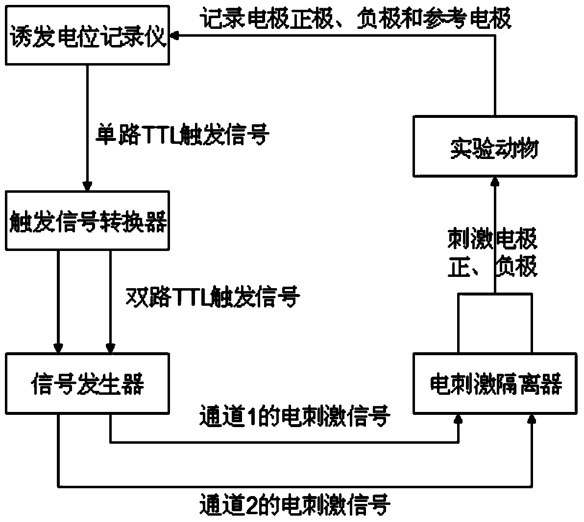
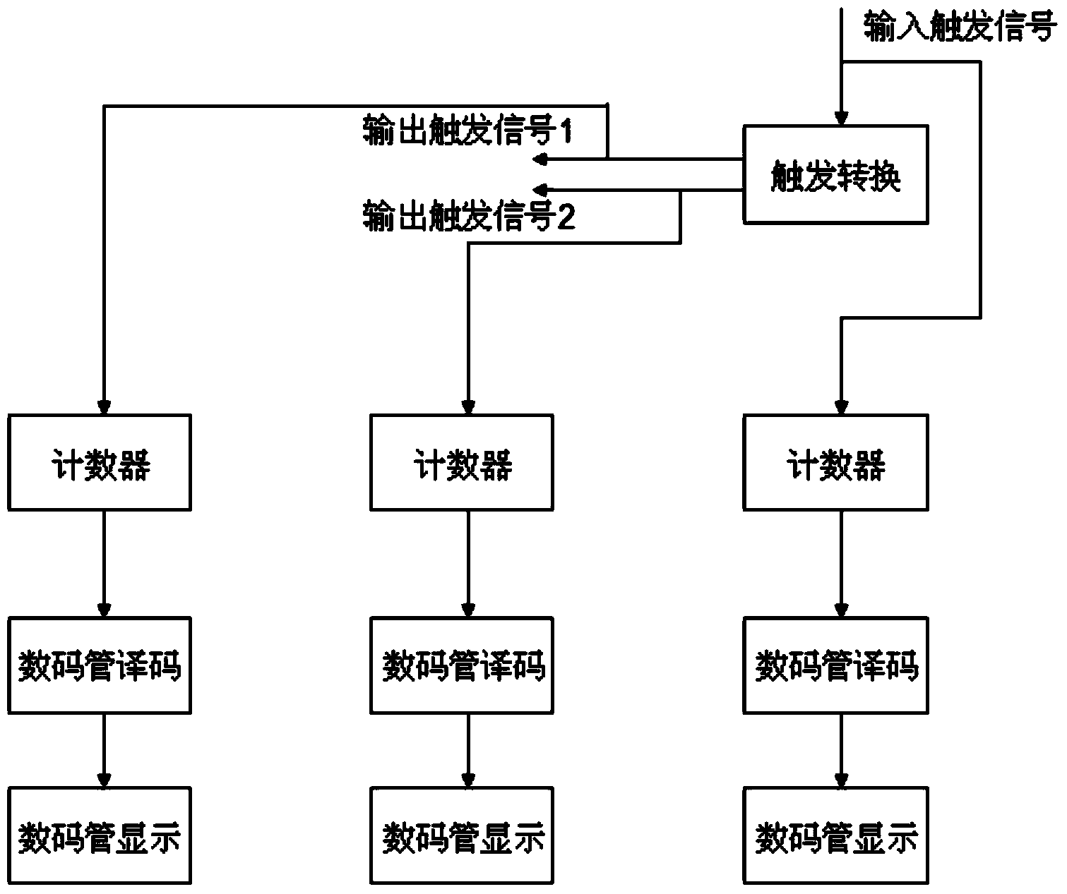
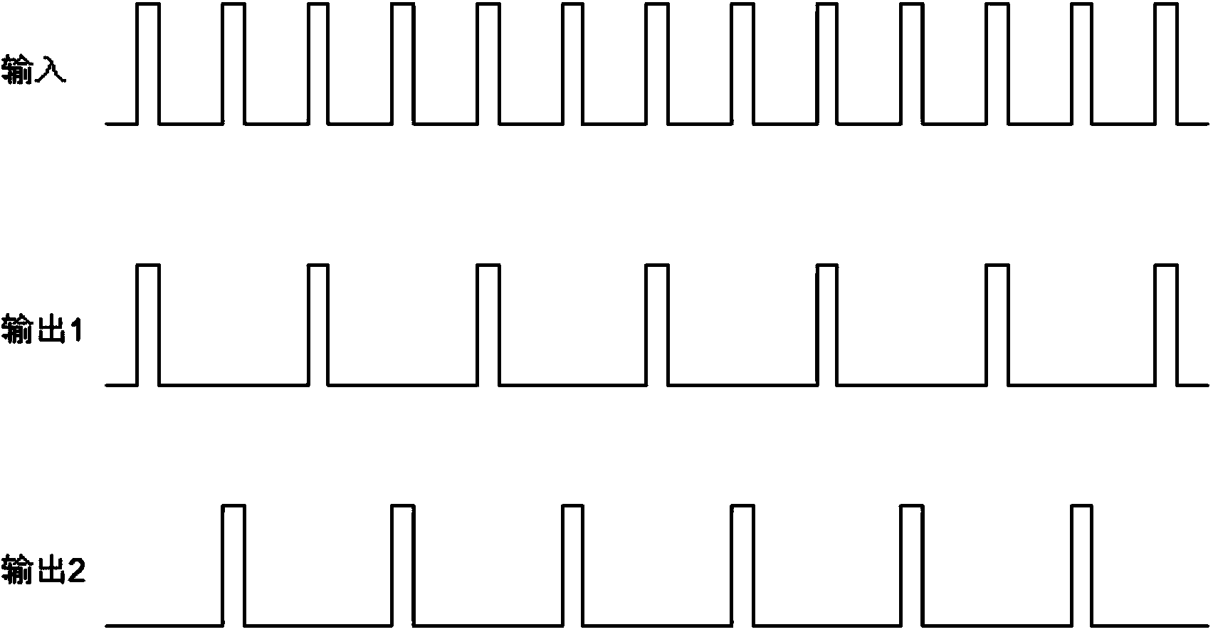
[0060] figure 1 Shown is a schematic diagram of the connection of each module of the electrical stimulation-induced brainstem frequency following response device of the present invention, the evoked potential recorder connects the coaxial line of the TTL trigger signal to the trigger signal converter, and the trigger signal converter converts the single-way trigger signal Convert to a two-way trigger signal, and connect the two-way trigger signal to the signal generator to control the channel 1 and channel 2 of the signal generator respectively. The signals of channel 1 and channel 2 of the signal generator are opposite in polarity The same signal (for example, s(i) represents the signal in channel 1, then the signal in channel 2 is -s(i)), the two signals pass through the elec...


PUM


Abstract

The invention discloses a device for evoking a brain stem frequency following reaction through electrical stimulation and a verification method. The device comprises an evoking potential recorder, the triggering signal output end of the evoking potential recorder converts input single path of signals into two paths of signals through a signal converter to control a channel (1) and a channel (2) of a generator, and electrical stimulation signals in the channel (1) and the channel (2) are opposite in polarity; the channel (1) and the channel (2) are connected to a stimulation electrode through an electrical stimulation signal isolator; the positive pole of the stimulation electrode is used for placing a round window niche of a user, and the negative pole of the stimulation electrode is used for making subcutaneous contact with the osseous external auditory canal; the positive pole of the evoking potential recorder is used for being placed in the center of a connecting line of the binaural calvarium of the user, the negative pole of the evoking potential recorder is used for making subcutaneous contact with the opposite side mastoid process of the user, and a reference electrode of the evoking potential recorder is used for making subcutaneous contact with the nasal tip of the user; the evoking potential recorder is connected with a signal processing module. The device can successfully evoke the brain stem frequency following reaction for an animal with the auditory periphery injured.

Description

technical field [0001] The invention belongs to the technical field of bioelectrophysiology, and in particular relates to a device and a verification method for inducing a brainstem frequency-following response. Background technique [0002] Frequency-following response is an auditory-evoked response derived from the brainstem of animals, which reflects the tracking and reproduction of the frequency of middle and low-frequency sound signals by phase-locked neurons (or groups of neurons) in the auditory system. Although it is the neural activity of the low-level auditory nucleus below the inferior colliculus, it reflects the functional integrity of the auditory pathway from one side. Not only that, the frequency following response is also affected by high-level cognitive processing activities such as language and attention. Therefore, the frequency following response is not only widely used in the study of the processing mechanism of the auditory system, but also has high cli...

Claims


Application Information

Patent Timeline
Patent Type & Authority Applications(China)
IPC IPC(8): A61B5/0484
Inventor 吴玺宏陈婧何文欣曲天书
Owner PEKING UNIV
Learn More