Leakage stoppage device used on naval vessels

A leak stopper and naval vessel technology, which is applied to the safety, transportation and packaging of naval vessels and ships, and can solve the problems of directly hitting the human body, unrecorded and unseen in patent documents, etc.

Inactive Publication Date: 2014-05-21
张繁荣
View PDF6 Cites 4 Cited by
  • Summary
  • Abstract
  • Description
  • Claims
  • Application Information

AI Technical Summary

Problems solved by technology

Therefore, people have invented many kinds of leak stoppers, such as the umbrella-type leak stopper, which uses the umbrella-type leak stopper to protrude from the leak hole when it is closed, and then spreads the leak stopper outside the ship, and then fixes the leak stopper on the It is a device on a ship to stop leaks. The disadvantage is that the water pressure in the leak hole is very high, and the water column goes straight to the body. At this time, it is difficult for the umbrella-type leak stopper to extend to the outside of the ship through the leak hole. Umbrella-typ...

Method used


Image

  • Leakage stoppage device used on naval vessels
  • Leakage stoppage device used on naval vessels
  • Leakage stoppage device used on naval vessels

Examples


Embodiment Construction

[0023] specific implementation plan

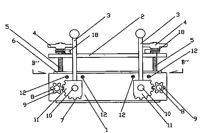
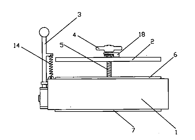
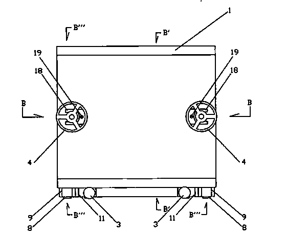
[0024] Attached below figure 1 , attached drawing 2, attached drawing 3, attached drawing 4, attached drawing 5, attached drawing 6, attached drawing 7, attached drawing 8, attached drawing Figure 9 , attached Figure 10 , attached Figure 11 Further description of the embodiment of the present invention: a leak stopper used on ships, the upper part of the square leak stopper seat 1 has a sealing plate 2 that can move up and down, and there is a sealing plate 2 on the left and right sides of the sealing plate 2. The sealing plate aperture 20 that screw 5 passes, the sealing plate hook 18 is installed above the sealing plate aperture 20, and screw 19 is fixed on the sealing plate hook 18 on the sealing plate 2. One end of the screw 5 passes through the central part of the seal plate hook 18 and the small hole 20 of the seal plate, and is fixed on the seat body 1 of the leak stopper, and the other end is bolted with a disc bolt 4, and th...


PUM


Abstract

The invention discloses a leakage stoppage device used on naval vessels and a schematic diagram of the leakage stoppage device. The leakage stoppage device has the advantages that impact pressure of water is reduced, no power supplies are needed, and the device is easy to operate, safe and reliable, can achieve fast leakage stoppage no matter what difference exists between sizes and shapes of water leakage holes and can be operated by just one person. A sealing plate is arranged on the upper portion of a square leakage stoppage device seat body, small sealing-plate holes are formed in the left side and right side of the sealing plate, and sealing-plate hooks are arranged above the small sealing-plate holes and are fixed to the sealing plate through screws. One end of each screw penetrates through the center of the corresponding sealing-plate hook and the corresponding small sealing-plate hole and is fixed to the leakage stoppage device seat body, and the other end of each screw is provided with a disc bolt in a bolting mode, and protruding circles are arranged below the disc bolts in a one-to-one correspondence mode and are in running-in relations with the sealing-plate hooks. The sealing plate is firmly hung to the protruding circles below the disc bolts through the hooks. Controllable strong magnets are arranged below the left side and the right side of the leakage stoppage device seat body respectively.

Description

technical field [0001] The invention relates to a leak stopper used on ships, in particular to a leak stopper using a magnetic pressure method, which belongs to the technical field of machinery and electronics. Background technique [0002] Due to the special mission of the ship, it is often hit by the enemy's shells and leaks during combat, which poses a serious threat to the safety and combat effectiveness of the ship. Quick and firm plugging has become a key issue. Therefore, people have invented many kinds of leak stoppers, such as the umbrella-type leak stopper, which uses the umbrella-type leak stopper to protrude from the leak hole when it is closed, and then spreads the leak stopper outside the ship, and then fixes the leak stopper on the It is a device on a ship to stop leaks. The disadvantage is that the water pressure in the leak hole is very high, and the water column goes straight to the body. At this time, it is difficult for the umbrella-type leak stopper to e...

Claims


Application Information

Patent Timeline
IPC IPC(8): B63B43/16
Inventor 张繁荣
Owner 张繁荣
Why Eureka
Try Eureka