A kind of anti-collision device for heavy photoelectric equipment

A technology of optoelectronic equipment and bumper, applied in the direction of non-rotational vibration suppression, etc., can solve the problem of no report of heavy optoelectronic equipment side bumper device, and achieve the effect of increasing mutual gap, maintaining stability and eliminating mutual gap.

Active Publication Date: 2015-08-26
南京捷诺环境技术有限公司
View PDF6 Cites 0 Cited by
  • Summary
  • Abstract
  • Description
  • Claims
  • Application Information

AI Technical Summary

Problems solved by technology

[0007] However, there is no report on the special side impact protection device for heavy-duty optoelectronic equipment

Method used


Image

  • A kind of anti-collision device for heavy photoelectric equipment
  • A kind of anti-collision device for heavy photoelectric equipment

Examples


Embodiment Construction

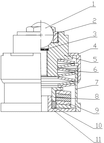
[0018] Such as figure 1 As shown, the anti-collision device for heavy-duty photoelectric equipment of the present invention, the main body is based on the shell 7, the upper end of the shell is threaded to install the screw cap 4, and the center of the screw cap top is provided with a hole, the connector 5 penetrates into the hole, and through the connecting The side flange of the head 5 is positioned with the screw cap 4 . There is a stepped hole on the upper part of the connecting head, and the oil tray 3 and the steel ball 1 are installed in the stepped hole, and the steel ball 1 is fixed and adjusted by screwing in the pressure ball cover 2. There is a stepped shaft at the lower part of the connecting head, and a set of discs A 6 are enclosed within the outer edge of the step shaft in the way of facing and reversed between two; the base plate 11 is installed at the bottom of the shell 7, and a tubular wire mesh pad 10 is housed between the base plate 11 and the anti-punchi...


PUM


Abstract

The invention discloses a bumper for heavy photoelectric equipment. An outer shell is used as the foundation of the bumper, a screw cap is arranged at the upper end of the outer shell, a hole is formed in the center of the top of the screw cap, a connector penetrates through the hole, a stepped hole is formed in the upper portion of the connector, a steel ball is arranged inside the stepped hole, and the steel ball is fixed and regulated by screwing a ball pressing cover in; a flange used for locating the screw cap is arranged on the side face of the connector; a stepped shaft is arranged on the lower portion of the connector, and the outer edge of the stepped shaft is sleeved with a set of discs A; a bottom board is arranged at the bottom end of the outer shell and is coaxially provided with a pressing preventing sleeve, and the top surface of the pressing preventing sleeve makes contact with the bottommost pair of discs A; the outer edge of the pressing preventing sleeve is sleeved with a set of discs B. The bumper has the advantages of achieving nonlinearity and unidirectional movement; it can be guaranteed that when the heavy photoelectric equipment bears large centrifugal force, inertial force and overturning moment, the bumper can instantly provide large rigidity so as to balance external force, and therefore the heavy photoelectric equipment is in a balanced working state.

Description

technical field [0001] The invention relates to an anti-collision device for photoelectric equipment, in particular to an anti-collision device for a low-frequency vibration isolation system for heavy-duty photoelectric equipment. When the vehicle-mounted and ship-borne optoelectronic equipment is subjected to horizontal impact, it can play the role of safe vibration isolation and buffer protection. Background technique [0002] With the development of modern military science and technology, the requirements for weapons and equipment are further improved, and the optoelectronic equipment is not only more and more sophisticated, but also the environment it faces is becoming more and more severe. For this reason, higher technical requirements and environmental adaptability are put forward for modern optoelectronic equipment. Require. Due to the poor adaptability of optoelectronic equipment to vibration and shock environments, in order for optoelectronic equipment to work norm...

Claims


Application Information

Patent Timeline
Patent Type & Authority Patents(China)
IPC IPC(8): F16F15/02
Inventor 季馨李刚施冠军季炯炯
Owner 南京捷诺环境技术有限公司
Why Eureka
Try Eureka