
Regulating valve for regulating the hydraulic volume flow

A volume flow, regulating valve technology, applied in the field of regulating valves, can solve the problems of increasing the overall volume and cost of door closers

Active Publication Date: 2017-11-24
DORMAKABA DEUT GMBH
View PDF5 Cites 0 Cited by
  • Summary
  • Abstract
  • Description
  • Claims
  • Application Information

AI Technical Summary

Problems solved by technology

Additional installation space and additional material are required for such an additional non-return valve, which increases the overall volume and costs of the door closer with the regulating valve and such a non-return valve

Method used


Image

  • Regulating valve for regulating the hydraulic volume flow
  • Regulating valve for regulating the hydraulic volume flow
  • Regulating valve for regulating the hydraulic volume flow

Examples


Embodiment Construction

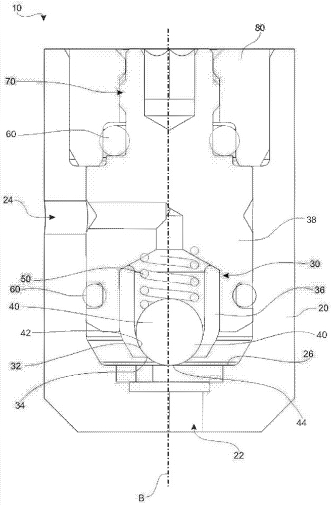
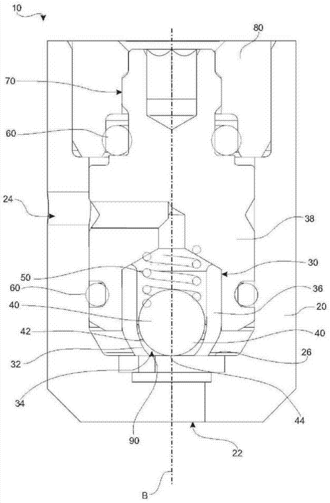
[0042] figure 1 and figure 2 A first embodiment of a regulating valve 10 according to the invention is shown. exist figure 1 In this regulating valve 10 is in a completely closed state, and figure 2 The fully open state is shown.

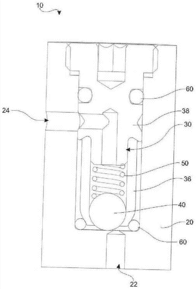
[0043] Such a control valve 10 is equipped with a pot-shaped and substantially cylindrical valve body 20 . In the interior of such a valve body 20 is accommodated a sleeve 30 which in this embodiment is constructed in two parts. Thus, such a socket 30 is provided by assembling the socket carrier 38 and the socket head 36 . The spring device 50 is supported between the adjustment member 40 and the sleeve carrier 38 of the sleeve 30 . Therefore achieved in figure 1 The adjustment member 40 is loaded with downward spring force. A sealing seat is formed between the adjusting member 40 and the sleeve 30 , which is provided by the contact of the outer sealing surface 42 of the adjusting member 40 with the inner sealing surface 32 of the sleeve 3...


PUM


Abstract

The valve (10) has a valve body (20) provided with a valve inlet (22) and a valve outlet (24). A movable sleeve (30) is provided with an inner sealing surface (32) in the valve body along a movement axis (B). A spring device (50) applies spring force on a regulating element (40) along direction of a sealing seat. The regulating element is extended in spring force direction through a sleeve opening (34). The regulating element is fixed on an inner wall (26) of the valve body during movement of the sleeve along a movement axis. An independent claim is also included for a method for controlling a hydraulic volume flow.

Description

technical field [0001] The invention relates to a regulating valve for regulating a hydraulic volume flow, a door closer for a door having at least one regulating valve, and a method for regulating a hydraulic volume flow. Background technique [0002] Regulating valves for regulating the hydraulic volume flow are generally known. Such regulating valves are used in particular in door closers in order to damp the closing movement due to the application of force. The damping characteristic is adjusted via a regulating valve. In the known regulating valves, a structure is usually provided as a needle valve, which provides an annular gap when the needle valve is moved in translation along the axis of movement. Depending on the size of the annular gap, larger or smaller fluid passages are provided with regard to the flow cross section. The smaller the flow cross-section, the stronger the associated damping of the damping characteristic. [0003] A disadvantage of the known re...

Claims


Application Information

Patent Timeline
Patent Type & Authority Patents(China)
IPC IPC(8): F16K47/16F16K17/04F16F9/16E05F3/12
CPCE05F3/12E05Y2900/132F16K15/044F16K17/0406
Inventor 亚历山大·赫尔维格
Owner DORMAKABA DEUT GMBH
Learn More