Splicing and fixing structure of block gauge and device adopting the structure

A technology of fixing structure and fixing device, applied in the field of measuring tool inspection, can solve the problems affecting the dimensional accuracy of the block gauge, the low degree of freedom of fitting, and the micro-deformation of the block gauge, and achieves high accuracy, high degree of freedom of fitting, straight line Uniform force and stable effect

Active Publication Date: 2016-09-14
恒洁利(南通)设备制造有限公司
View PDF5 Cites 0 Cited by
  • Summary
  • Abstract
  • Description
  • Claims
  • Application Information

AI Technical Summary

Problems solved by technology

In the prior art, the block gauge clips are generally used to splice or fix the block gauges, but these block gauge clips generally have the following defects: 1. The application is limited and limited by the size of the block gauge clips; 2. The lamination degree of freedom is not enough High, and the error is large; 3. The way of fitting is to use the hand lock screw to compress, and the pressing force can only be determined by the feel, which is easy to cause the block gauge to be too stressed and cause micro deformation to affect the dimensional accuracy of the block gauge; 4. For slightly longer Block gauge, there is a possibility of slight deformation

Method used


Image

  • Splicing and fixing structure of block gauge and device adopting the structure
  • Splicing and fixing structure of block gauge and device adopting the structure
  • Splicing and fixing structure of block gauge and device adopting the structure

Examples


Embodiment 1

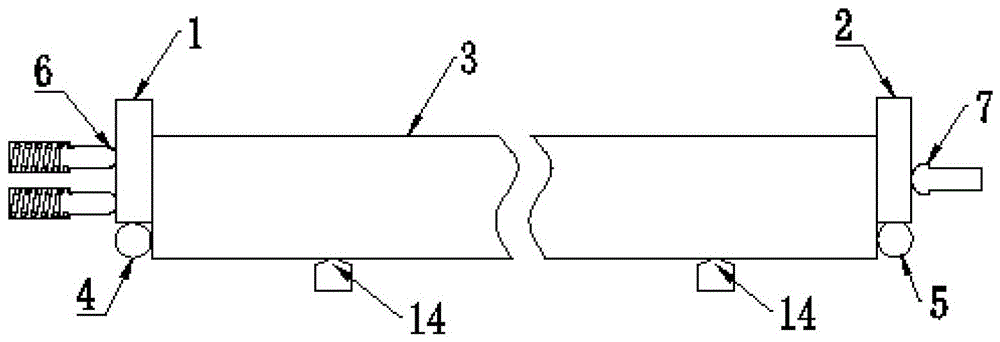
[0035] Embodiment 1: a splicing and fixing structure of a block gauge, such as figure 1 As shown, the third gauge 3 is located between the first gauge 1 and the second gauge 2, and the head end of the third gauge 3 is in surface contact with the end of the first gauge 1, so The end of the third gauge 3 is in surface contact with the head end of the second gauge 2, and a first support 4 for supporting the first gauge is provided below the first gauge 1. Support 4 is a line support, and the second support 5 for supporting the second block gauge is provided below the second block gauge 2. The second support 5 is a line support, and the head end of the first block gauge 1 is provided with There is a first abutting piece 6 for pressing the first gauge 1 towards the direction of the third gauge 3, the first abutting piece 6 is in point contact with the head end of the first gauge 1, so The end of the second gauge 2 is provided with a second abutting member 7 for pressing the second...

Embodiment 2

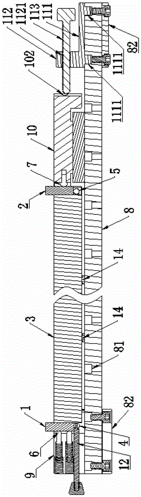
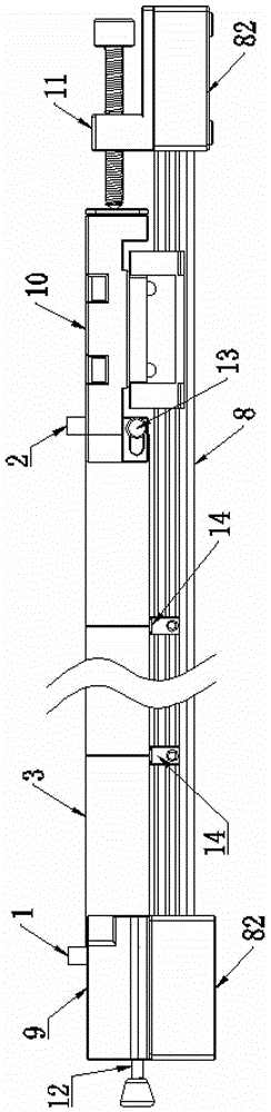
[0038] Embodiment 2: a splicing and fixing device of a block gauge, such as Figure 2 to Figure 6 As shown, the splicing and fixing structure of the block gauge described in Embodiment 1 is also provided with a linear guide rail 8, a first block gauge seat 9, a second block gauge seat 10 and a fastener 11, and the first block gauge The seat 9 and the second block gauge seat 10 are located on the linear guide rail 8, and the first block gauge seat 9 is a fixed block gauge seat fixed on the linear guide rail 8, and the second block gauge seat is A movable block gauge seat capable of moving along the linear guide rail 8, a first slot 91 is provided on the first block gauge seat 9, a second slot 101 is provided on the second block gauge seat 10, the Both the first slot 91 and the second slot 101 are parallel to the linear guide rail 8, and the opening of the first slot 91 is opposite to the opening of the second slot 101, and the first gauge 1 and the first end of the third gauge...

Embodiment 3

[0045] Embodiment 3: This embodiment discloses a splicing and fixing device for a block gauge. The splicing and fixing device for a block gauge in this embodiment is roughly the same in structure as the splicing and fixing device for a block gauge in Embodiment 2. The difference is that the third block gauge 3 of this embodiment is formed by splicing several first single block gauges 31 and several second single block gauges 32 along their nominal measurement directions, and the first single block gauge 31 and the second single block gauge 32 are interlaced, and the adjacent first single block gauge 31 and the second single block gauge 32 are in surface contact, and the head end and the end of the third block gauge 3 are both The first single block gauge 31, the joint of the first single block gauge 31 and the second single block gauge 32 is provided with a third block gauge seat 15, on the third block gauge seat 15 A third slot 151 is opened, and the third slot 151 penetrates...


PUM


Abstract

The invention discloses a splicing and fixing structure of block gauges and a device utilizing same. The block gauges are in surface contact with each other, line or point support is formed at the bottoms of the block gauges, the block gauges which are arranged on the bilateral sides are of point contact abutting structures, and accordingly the degrees of freedom of attachment is high, the accuracy is high, and the use is scientific and good in comparison with block gauge clamps in the prior art; the one side of block gauges of the block gauges which are arranged on the bilateral sides are of point contact elastic abutting structures, the fixed attachment pressing force is provided, and accordingly the size accuracy of the block gauges cannot be affected by the micro deformation caused by too large force of the block gauges; a linear guide rail is good in linearity and moves without radial clearance, mobile block gauge seats move along the direction of the linear guide rail, and accordingly the linear force is uniform and stable; in addition, block gauge supports which are used for performing supporting are arranged corresponding to the positions of supporting points of the block gauges and accordingly the micro deformation of the block gauges especially the long gauge blocks can be effectively avoided.

Description

technical field [0001] The invention belongs to the field of measuring tool inspection in the industrial technology, and in particular relates to a structure capable of splicing or fixing a plurality of block gauges and a device adopting the structure. Background technique [0002] The block gauge is simply a square block gauge, so it is called a block gauge. A set of block gauges is composed of blocks of different specifications and sizes, generally made of steel, with very high precision. To meet the needs of various workpiece size measurement. When measuring, it may be necessary to splice multiple block gauges along their lengths to achieve the required measurement length, or to fix the block gauges for easy measurement. In the prior art, the block gauge clips are generally used to splice or fix the block gauges, but these block gauge clips generally have the following defects: 1. The application is limited and limited by the size of the block gauge clips; 2. The lamina...

Claims


Application Information

Patent Timeline
Patent Type & Authority Patents(China)
IPC IPC(8): G01B3/30
Inventor 甘太喜
Owner 恒洁利(南通)设备制造有限公司
Why Eureka
Try Eureka