Clamping jig

A jig and clamping technology, applied in the field of jig, can solve the problems of poor clamping effect, deformation of clamping structure, complex structure, etc., and achieve the effect of easy clamping operation and small structure occupied space.

Inactive Publication Date: 2019-06-25
惠州市世育五金制品有限责任公司
View PDF10 Cites 0 Cited by
  • Summary
  • Abstract
  • Description
  • Claims
  • Application Information

AI Technical Summary

Problems solved by technology

The conventional clamping jig has the following problems, such as single use of the clamping jig, high versatility of the clamping jig but relatively complicated structure, when the clamping jig is used to clamp the two ends of the long structure, due to The clamping force is strong, so a slight misalignment in the direction of the force will lead to slight deformation of the clamping structure, which can easily lead to poor clamping effect, etc., and other problems

Method used


Image

  • Clamping jig
  • Clamping jig

Examples


Embodiment Construction

[0017] A number of embodiments of the present invention will be disclosed in the following figures. For the sake of clarity, many practical details will be described together in the following description. It should be understood, however, that these practical details should not be used to limit the invention. That is, in some embodiments of the invention, these practical details are not necessary. In addition, for the sake of simplifying the drawings, some well-known structures and components are shown in a simple schematic manner in the drawings.

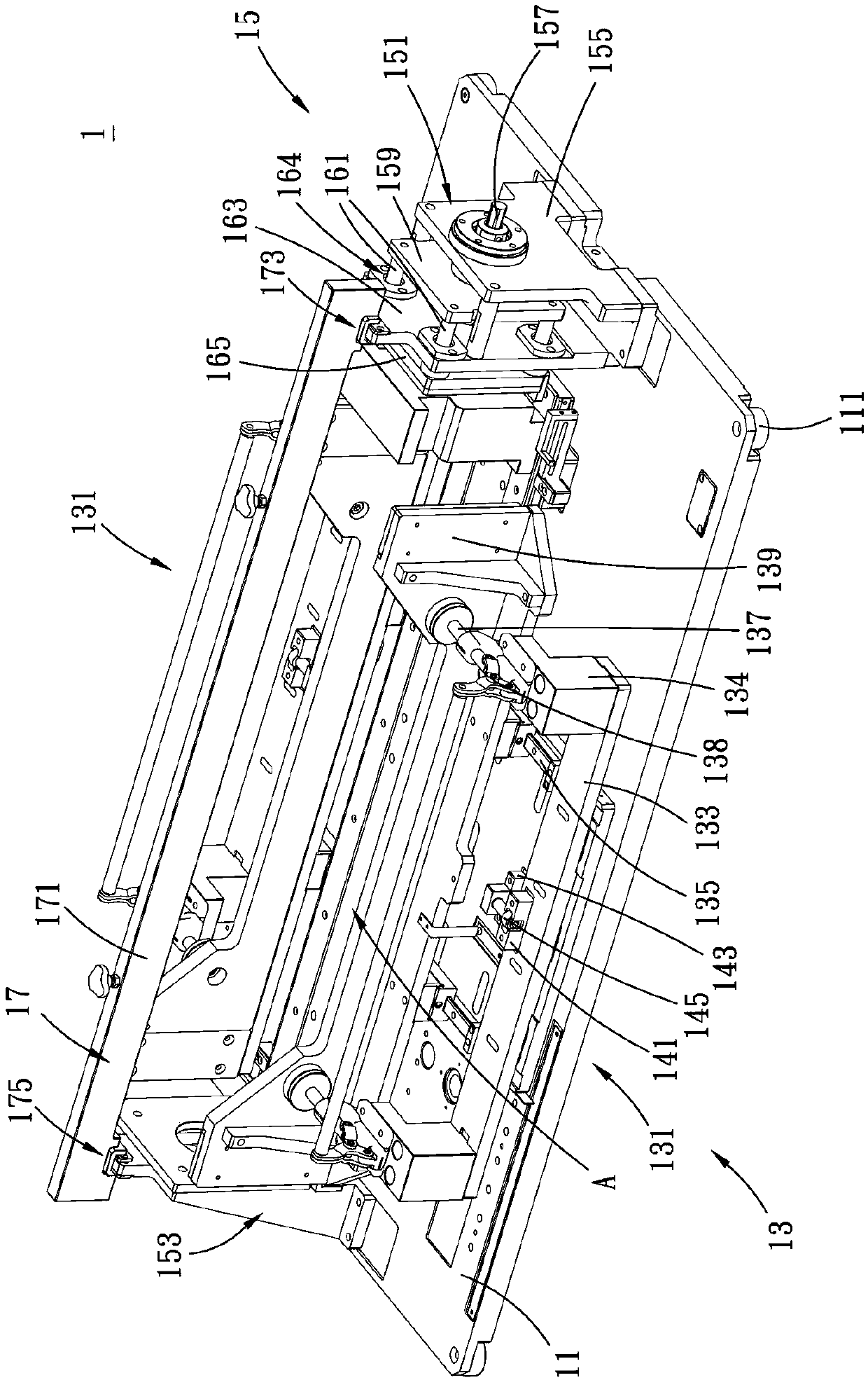
[0018] see figure 1 , which is a three-dimensional schematic view of the clamping jig of the present invention. As shown in the figure, this embodiment provides a clamping jig 1 , which is a tool for clamping products in the product manufacturing process. In this embodiment, the clamping jig 1 is described below using welding of hard shell battery products as an embodiment, but this description does not limit the clamping jig 1 ...


PUM


Abstract

The invention discloses a clamping jig. The clamping jig comprises a base, a side pressing holding structure, a pressing holding structure and a fixing piece. The base is provided with a machining area, and the object to be machined is placed in the machining area. The side pressing holding structure and the pressing holding structure separately correspond to the machining area, the extrusion directions of the side pressing holding structure and the pressing holding structure face into the machining area, and the extrusion directions of the side pressing holding structure and the pressing holding structure are different. The side pressing holding structure and the pressing holding structure extrude the object to be machined in the machining area, wherein the side pressing holding structureand the pressing holding structure can be applied to products with different lengths and widths, furthermore, when the pressing holding structure needs to apply a larger pressing holding force, the problem that the extrusion machining state of a product is affected due to micro-deformation of the pressing holding structure is prone to being caused, and therefore, the fixing piece can be used forstrengthening the structural strength of the pressing holding structure.

Description

technical field [0001] The invention relates to a jig, in particular to a clamping jig. Background technique [0002] Taking the similar clamping fixtures on the market at present, most of them will have the following three problems. The first point is that the applicable products of the fixture are relatively single, the scope of use of the fixture is limited, or it is more versatile as a tool. Tall fixtures may require more parts and a larger overall structure. The second point is that when the clamping force is large, the limit components at both ends of the battery module (that is, at both ends of the long side) may be slightly dislocated due to the applied force, resulting in micro-deformation of the structure, which affects the clamping fixture clamping effect. The third point is that the structure of the side pressing mechanism of the battery module is relatively rigid, the adjustability is not high, and it takes up a lot of space. The known clamping jig has the ab...

Claims


Application Information

Patent Timeline
Patent Type & Authority Applications(China)
IPC IPC(8): B23K37/04B25B11/00
Inventor 彭沁洙
Owner 惠州市世育五金制品有限责任公司
Why Eureka
Try Eureka