electric shoe brush
An electric brush and shoe polish technology, applied in the direction of cleaning boots and shoes, cleaning equipment, household appliances, etc., can solve the problems of low work efficiency, waste of shoe polish, troublesome operation, etc., and achieve the effect of precise control, avoidance of waste and convenient operation.
- Summary
- Abstract
- Description
- Claims
- Application Information
AI Technical Summary
Problems solved by technology
Method used
Image
Examples
Embodiment 1
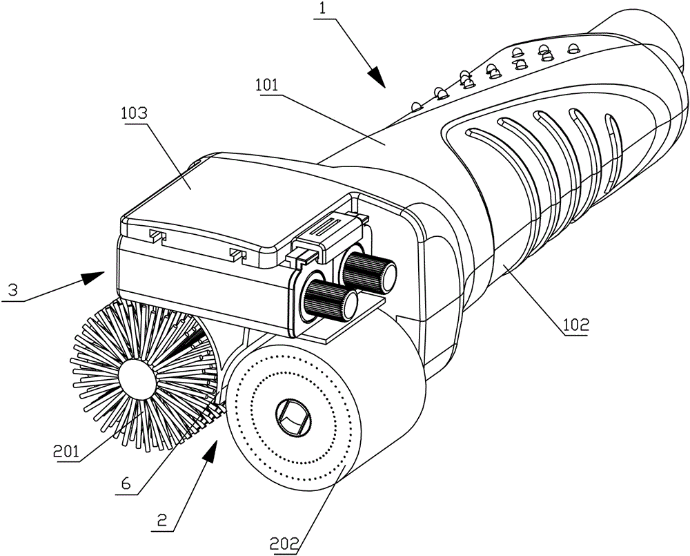
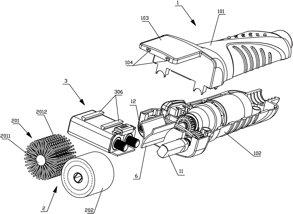
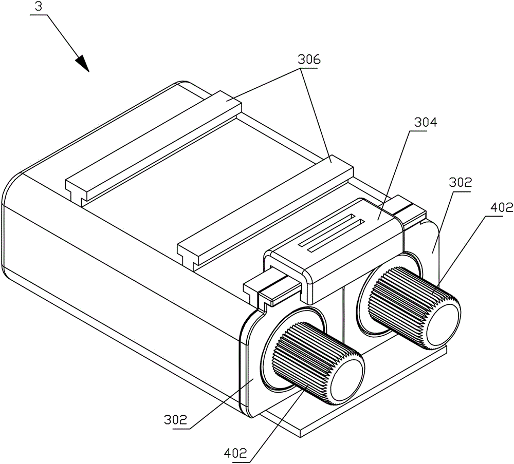
[0033] Depend on figure 1 , figure 2As shown, the electric shoe brushing device of the present invention includes a handle portion 1, a brush body 2 and an oil storage device 3, and the brush body 2 includes a shoe polish brush roller 201 and a polishing brush roller 202, and the shoe polish brush roller 201 and the polishing brush roller 202 and the oil storage device 3 are all arranged at one end of the handle part 1, the axes of the shoe polish brush roller 201 and the polishing brush roller 202 are parallel, the shoe polish brush roller 201 and the polishing brush roller 202 are horizontally arranged in parallel, and the oil storage device 3 is arranged on the shoe polish brush roller Above the roller 201, one end of the handle portion 1 is provided with a mounting plate 103, the mounting plate 103 is located above the shoe polish brush roller 201 and the polishing brush roller 202, and the lower surface of the mounting plate 103 is provided with two extending along the l...
Embodiment 2
[0041] Compared with the first embodiment, this embodiment differs in that the installation method of the oil storage device 3 is different, by Figure 8 , Figure 9 As shown, one end of the handle portion 1 is provided with a first support portion 105 extending along the width direction of the handle portion 1, and the end of the mounting plate 103 away from the handle portion 1 is provided with a downwardly extending limiting plate 107, and the limiting plate 107 The lower end of the lower end is provided with the second support part 106 parallel to the first support part 105, and the installation plate 103, the limit plate 107, the first support plate 105, and the second support plate 106 form a space for accommodating the oil storage device 3. For the oil storage device 3 , insert the oil storage device under the mounting plate 103 along the width direction of the handle part 1 .
Embodiment 3
[0043] Compared with Embodiment 1, this embodiment differs in that the structure and installation method of the oil storage device are different. Figure 10 , Figure 11 As shown, the mounting plate 103 is provided with a mounting hole 108, and the oil storage device 3 is fixed in the mounting hole 108, by Figure 12 , Figure 13 , Figure 14 , Figure 15 As shown, the cavity opening 303, the cavity cover 302, and the knob 402 are located on the upper surface of the oil storage device 3, the screw rod 4 is vertically arranged, the pressure plate 403 and the limit plate 401 are horizontally arranged, the opening 5 is located at the bottom of the cavity 301, and the baffle plate 6 is a flat plate, and the baffle plate 6 is fixed on the bottom of the oil storage device 3. The baffle plate 6 is arranged between the shoe polish brush roller 201 and the polishing brush roller 202. In addition, the pressure plate 403 is provided with a seal fitting with the inner wall of the cavit...
PUM
 Abstract
Description
Claims
Application Information
 - R&D
- Intellectual Property
- Life Sciences
- Materials
- Tech Scout
- Unparalleled Data Quality
- Higher Quality Content
- 60% Fewer Hallucinations
Browse by: Latest US Patents, China's latest patents, Technical Efficacy Thesaurus, Application Domain, Technology Topic, Popular Technical Reports.
© 2025 PatSnap. All rights reserved.Legal|Privacy policy|Modern Slavery Act Transparency Statement|Sitemap|About US| Contact US: help@patsnap.com


