Constant temperature and humidity testing machine

A technology of constant temperature and humidity test and testing machine, which is used in laboratory utensils, heating or cooling equipment, shells or chambers, etc. Shen and other problems, to meet the low flow rate test requirements, the gas flow is uniform, and the effect of avoiding airflow turbulence

Active Publication Date: 2016-02-10
DONGGUAN CITY SIMPLEWELL TECH
View PDF7 Cites 2 Cited by
  • Summary
  • Abstract
  • Description
  • Claims
  • Application Information

AI Technical Summary

Problems solved by technology

When working, the gas will flow between the test chamber and the circulating air duct under the action of the circulating fan. However, during the flow of the gas, most of the gas will sink and gather at the bottom of the circulating air duct. When the gas returns to the test chamber, the gas flow velocity at the bottom of the test chamber will be relatively large, which is prone to air flow disturbance, making the constant temperature and humidity testing machine unable to meet the low flow rate test requirements

Method used


Image

  • Constant temperature and humidity testing machine
  • Constant temperature and humidity testing machine
  • Constant temperature and humidity testing machine

Examples


Embodiment 1

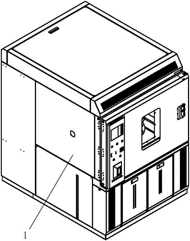
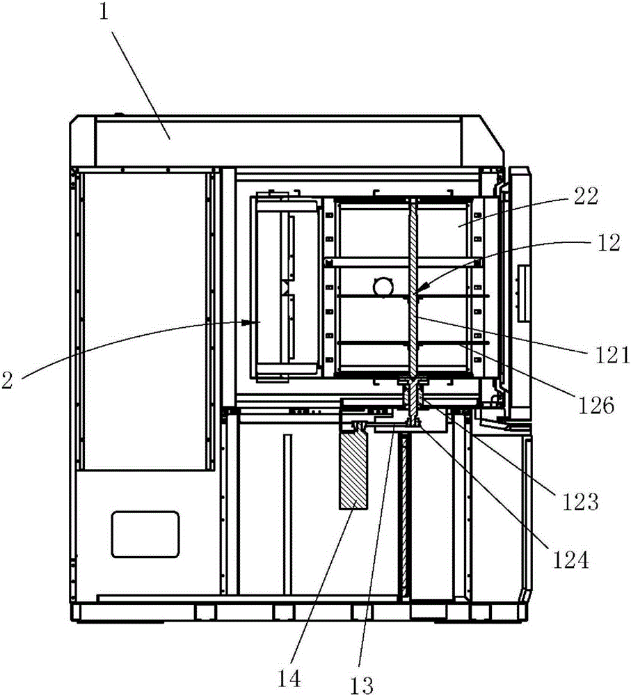
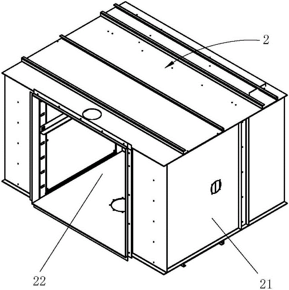
[0029] Please refer to Figure 1 to Figure 7 , a constant temperature and humidity testing machine is shown in the figure, including a testing machine shell 1, a test box 2 is installed inside the testing machine shell 1, and the test box 2 includes a box body 21 and a test chamber arranged inside the box body 21 22. A circulating air duct 23 is formed between the box body 21 and the test chamber 22, and the circulating air duct 23 communicates with the test chamber 22. The interior of the circulating air duct 23 is equipped with an evaporator 3, a heater 4, a humidifier 5 and a circulating air duct. The fan 6, the air inlet and the air outlet of the circulating air duct 23 are respectively equipped with a gas uniform distribution device 7, and the gas uniform distribution device 7 includes a first mesh plate 71 and a second mesh plate arranged in sequence toward the inner direction of the circulating air duct 23 72. The first mesh plate 71 and the second mesh plate 72 are res...

Embodiment 2

[0039] Embodiment 2 of the present invention provides a constant temperature and humidity testing machine, whose structure is mostly the same as that of Embodiment 1 above, and will not be repeated here. Decrease from top to bottom. Such as Figure 9 As shown, in this embodiment, the second screen unit 72 includes a first screen unit 721 , a second screen unit 722 and a third screen unit 723 arranged in sequence from top to bottom. Wherein, the first screen unit 721, the second screen unit 722 and the third screen unit 723 are integrally formed, the number of mesh holes of the first screen unit 721 is greater than the number of the second screen unit 722, and The number of meshes of the second screen unit 722 is more than the number of meshes of the third screen unit 723, preferably, the first screen unit 721, the second screen unit 722 and the third screen unit 723 The meshes have the same pore size.

[0040] In summary, during work, the gas in the test chamber 22 enters t...


PUM


Abstract

The invention discloses a constant-temperature and constant-humidity test machine. The constant-temperature and constant-humidity test machine comprises a test machine casing, wherein a test box is arranged in the test machine casing, the test box comprises a box body and a test chamber which is arranged in the box body, a circulating air duct is formed between the box body and the test chamber, the circulating air duct is communicated with the test chamber, gas uniform distribution devices are respectively arranged at an air inlet and an air outlet of the circulating air duct, each gas uniform distribution device comprises a first meshed plate and a second meshed plate which are sequentially arranged towards the interior of the circulating air duct, a plurality of mesh holes are respectively formed in the first meshed plate and the second meshed plate, and the hole diameters of the mesh holes of the second meshed plate are sequentially reduced from the upper part to the lower part, or the number of the mesh holes of the second meshed plate is sequentially reduced from the upper part to the lower part. The flow speed of gas from the upper part to the lower part can be controlled through the first meshed plate and the second meshed plate so as to ensure uniform gas flow in the test chamber and avoid air flow turbulence phenomena. As a result, the constant-temperature and constant-humidity test machine can meet the requirement of low-flow rate tests.

Description

technical field [0001] The invention relates to the technical field of testing devices, more specifically, to a constant temperature and humidity testing machine. Background technique [0002] The constant temperature and humidity testing machine is a kind of equipment that tests the performance of the product under a certain constant temperature and humidity state to check whether the performance of the product meets the requirements of the relevant standards. [0003] The shell of the existing constant temperature and humidity testing machine is generally equipped with a test box. The test box includes a box body and a test cabin arranged inside the box body. A circulating air duct is formed between the box body and the test cabin. The test chamber is connected, and the interior of the circulating air duct is equipped with an evaporator, a heater, a humidifier and a circulating fan. When working, the gas will flow between the test chamber and the circulating air duct unde...

Claims


Application Information

Patent Timeline
Patent Type & Authority Patents(China)
IPC IPC(8): B01L1/00B01L7/00
Inventor 黄清帅夏可瑜
Owner DONGGUAN CITY SIMPLEWELL TECH
Why Eureka
Try Eureka