Supercharge Your Innovation With Domain-Expert AI Agents!

Ink box, ink box chip and light-emitting control method and device of ink box chip

An ink cartridge chip and light-emitting control technology, applied in printing devices, printing, etc., can solve the problems of difficult process requirements and design, high manufacturing cost, etc., and achieve the effect of low process requirements and design difficulty, and low manufacturing cost

Active Publication Date: 2014-05-28
APEX MICROELECTRONICS CO LTD
View PDF9 Cites 10 Cited by
  • Summary
  • Abstract
  • Description
  • Claims
  • Application Information

AI Technical Summary

Problems solved by technology

[0005] However, if the above-mentioned lighting control method is used to prompt the user for the state of the ink cartridge, the inkjet imaging device usually sends light control instructions to the ink cartridge chip at a relatively high sending frequency, which requires the ink cartridge to be capable of frequently receiving the light emitted by the inkjet imaging device. Ability to control commands
This kind of ink cartridge with the ability to frequently receive the light control instructions sent by the inkjet imaging device has relatively high process requirements and design difficulties, resulting in high manufacturing costs

Method used


Image

  • Ink box, ink box chip and light-emitting control method and device of ink box chip
  • Ink box, ink box chip and light-emitting control method and device of ink box chip
  • Ink box, ink box chip and light-emitting control method and device of ink box chip

Examples


Embodiment 1

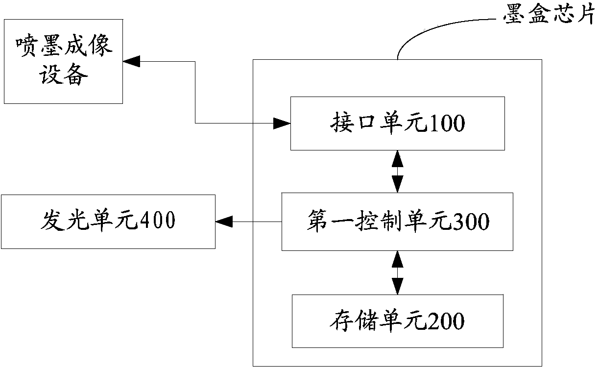
[0076] figure 1 It is a structural schematic diagram of the ink cartridge chip of Embodiment 1 of the present invention, combined with figure 1 The ink cartridge chip of Embodiment 1 of the present invention will be described in detail. Such as figure 1 As shown, the ink cartridge chip includes: an interface unit 100 , a storage unit 200 , and a first control unit 300 . Wherein, the first control unit 300 is respectively connected with the interface unit 100 and the storage unit 200 for realizing signal transmission and control.

[0077] Wherein, the interface unit 100 is used to realize the connection between the ink cartridge chip and the inkjet imaging device;

[0078] The storage unit 200 is used for storing the information of the state of the ink cartridge;

[0079] The first control unit 300 is used to determine whether the inkjet imaging device is currently in the stage of prompting the state of the ink cartridge when the inkjet imaging device starts to supply power...

Embodiment 2

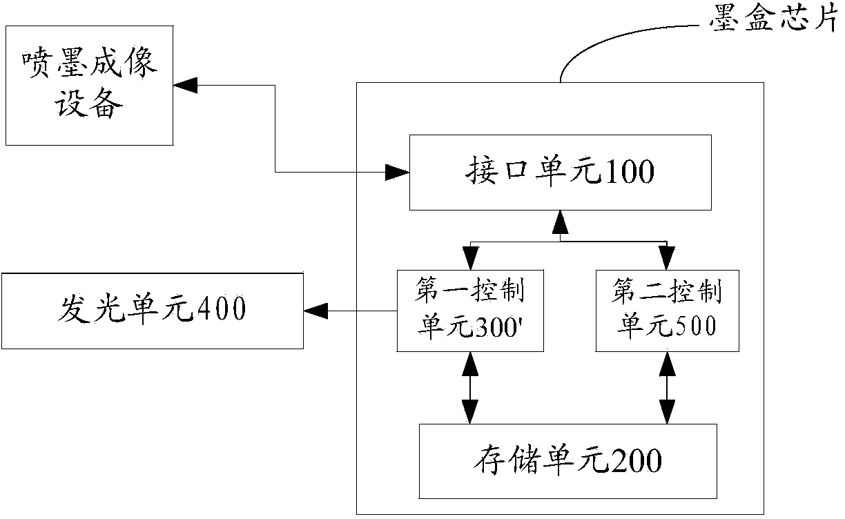
[0118] The ink cartridge chip described in Embodiment 2 has many similarities with the ink cartridge chip described in Embodiment 1. For the sake of brevity, this embodiment focuses on the differences. For the similarities, please refer to the description of Embodiment 1.

[0119] Such as figure 2 As shown, the ink cartridge chip described above may also include a second control unit 500, which is connected to the interface unit 100 and the storage unit 200 respectively, and the second control unit 500 is used to The received read-write control instruction sent by the inkjet imaging device executes read-write operations on the storage unit. In this embodiment, the function of the first control unit 300' is only to realize the control operation of the light control command, and not to control the read and write control command. Instead, the second control unit 500 realizes the control operation of the light control command. .

[0120]Based on the ink cartridge chip described...

Embodiment 3

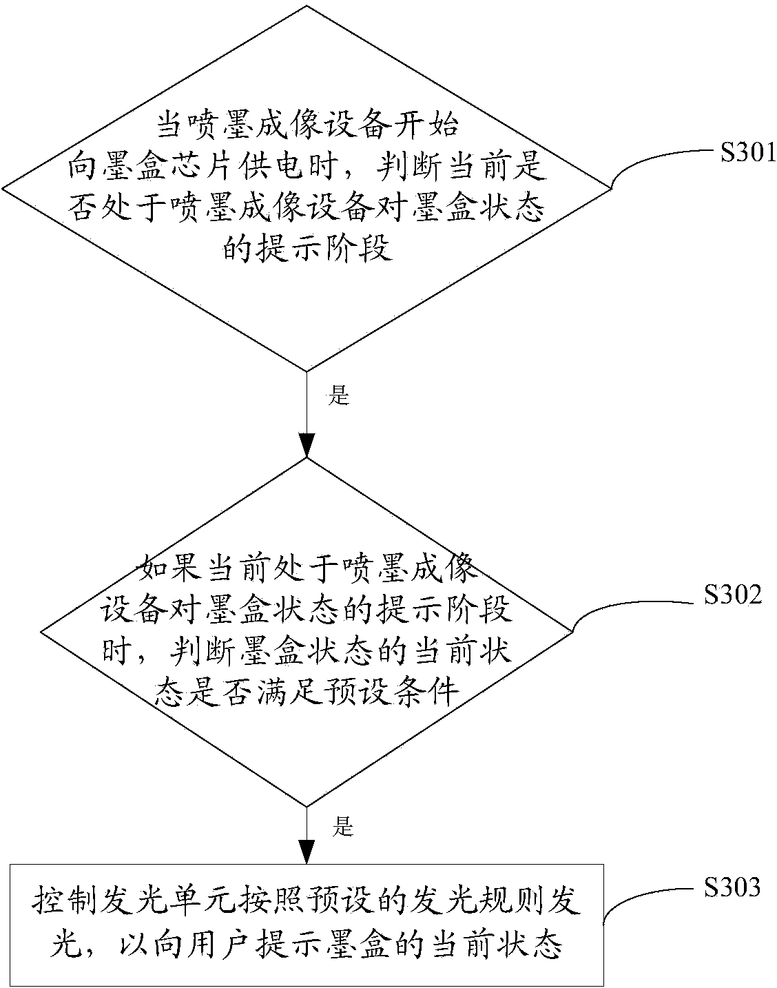
[0123] Such as image 3 As shown, the luminescence control method of the ink cartridge chip comprises the following steps:

[0124] S301. When the inkjet imaging device starts to supply power to the ink cartridge chip, determine whether it is currently in the stage of prompting the inkjet imaging device for the state of the ink cartridge:

[0125] As described in Embodiment 1 or Embodiment 2, the ink cartridge chip described in this embodiment of the present invention includes an interface unit 100 , a storage unit 200 and a first control unit 300 .

[0126] As described in Embodiment 1, there are multiple methods for the first control unit 300 to determine whether the inkjet imaging device is currently in the stage of prompting the state of the ink cartridge. details as follows:

[0127] The first method: by judging whether the type of the light control command is the preset light control command type:

[0128] Specifically, firstly, the interface unit 100 receives the lig...


PUM


Abstract

The invention provides a light-emitting control method of an ink box chip. The control method comprises the steps that when ink jet imaging equipment starts to provide power for the ink box chip, whether a current stage is the hinting stage of the ink jet imaging equipment on an ink box state is judged; and if yes, whether the current ink box state accords with a preset condition, if yes, light is emitted according to a preset light-emitting rule, and the current ink box state is hinted for a user. According to the light-emitting control method, the technology requirement and the designing difficulty of the ink box chip can be well lowered. The invention further provides a light-emitting control device of the ink box chip. In addition, the invention provides the ink box chip and an ink box.

Description

technical field [0001] The invention relates to the technical field of inkjet imaging, in particular to an ink cartridge, an ink cartridge chip and a method and device for controlling light emission thereof. Background technique [0002] An inkjet image forming device includes a device main body and a detachable ink cartridge. An optical receiver is arranged inside the main body of the existing inkjet imaging device, and a light emitter is arranged on the ink cartridge, and the light-emitting control of the ink cartridge or the ink cartridge chip is realized through the method of optical verification. [0003] The specific implementation of the lighting control method is as follows: [0004] The inkjet imaging device sends a corresponding control instruction to the ink cartridge, the control instruction includes the identification information of the ink cartridge, and the corresponding ink cartridge controls the lighting or extinguishing of the light emitter on it according...

Claims


Application Information

Patent Timeline
IPC IPC(8): B41J2/175B41J29/393
CPCB41J2/17546
Inventor 孙学进
Owner APEX MICROELECTRONICS CO LTD
Features
  • R&D
  • Intellectual Property
  • Life Sciences
  • Materials
  • Tech Scout
  • Unparalleled Data Quality
  • Higher Quality Content
  • 60% Fewer Hallucinations
Learn More