Cylindrical metallographic specimen holder

A metallographic sample and columnar technology, which is applied to measuring devices, instruments, scientific instruments, etc., can solve problems such as time-consuming, and achieve the effects of wide application range, safe use and simple structure.

Inactive Publication Date: 2016-08-24
HENAN UNIV OF SCI & TECH
View PDF9 Cites 0 Cited by
  • Summary
  • Abstract
  • Description
  • Claims
  • Application Information

AI Technical Summary

Problems solved by technology

[0003] The purpose of the present invention is to provide a cylindrical metallographic sample fixture to solve the time-consuming and time-consuming problems of the existing cylindrical metallographic sample using the mosaic clamping method

Method used


Image

  • Cylindrical metallographic specimen holder
  • Cylindrical metallographic specimen holder
  • Cylindrical metallographic specimen holder

Examples


Embodiment Construction

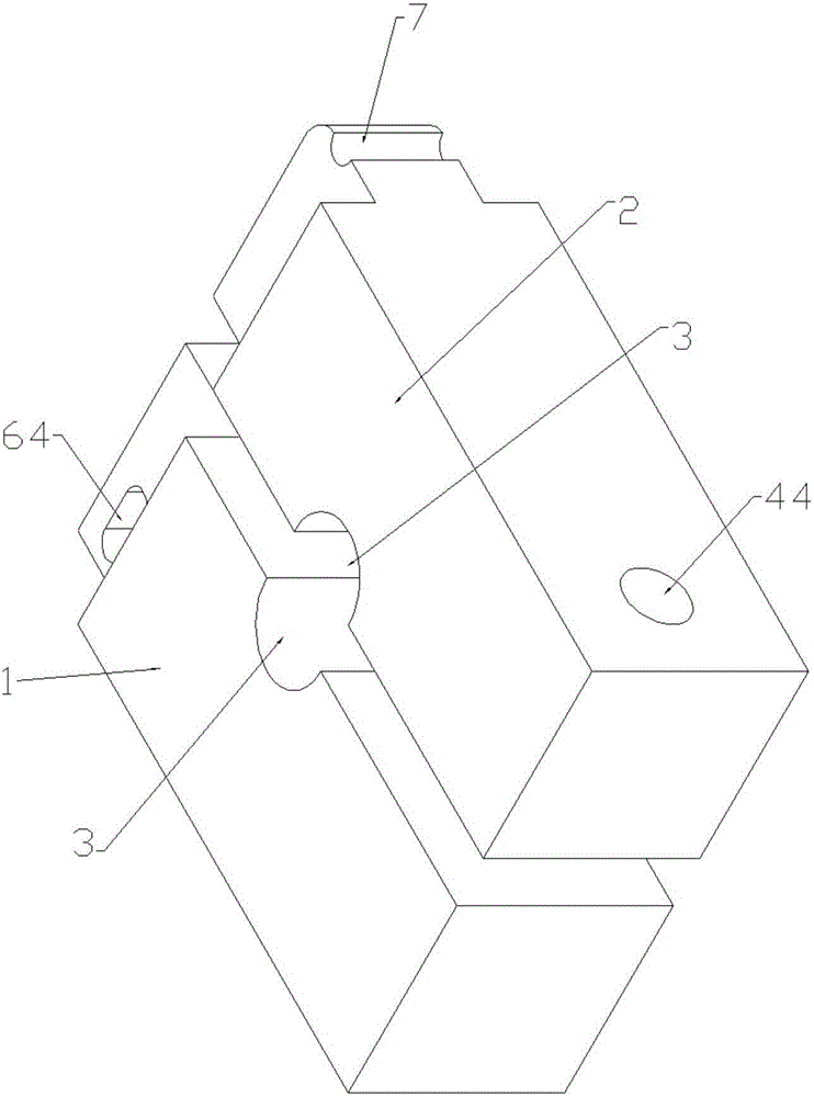
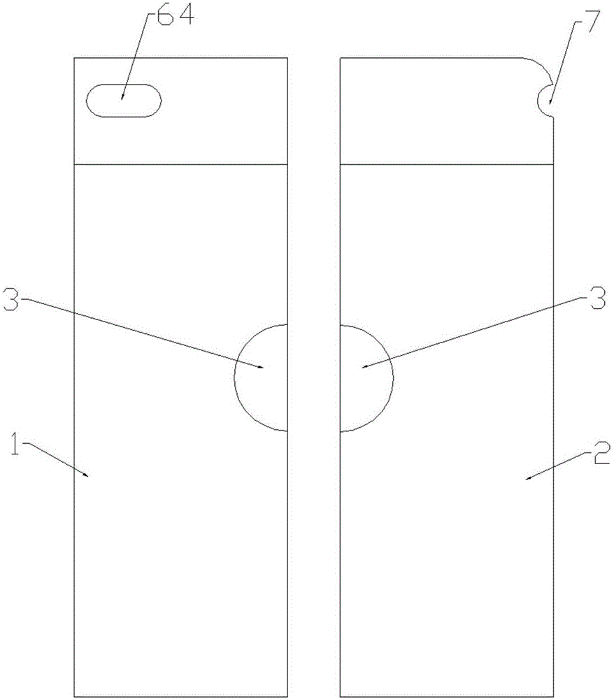
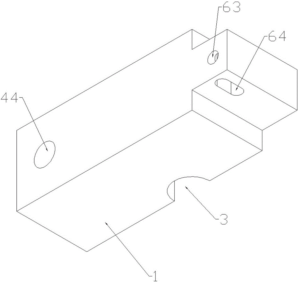
[0026] Embodiment 1 of the present invention, such as Figure 1-14 As shown: the cylindrical metallographic sample holder includes a left plate 1 and a right plate 2. A clamping opening 3 is provided on the side where the left side plate 1 and the right side plate 2 are close to each other, a clamping mechanism is provided at one end of the upper end and the lower end of the clamp, and an elastic ring sleeve 5 is provided at the other end.

[0027] In this embodiment, the clamping mechanism is arranged at the lower end of the clamp, and the elastic ring sleeve 5 is arranged at the upper end of the clamp. In other embodiments, the positions of the clamping mechanism and the elastic ring sleeve can also be reversed, the clamping mechanism is set at the upper end of the clamp, and the elastic ring sleeve is set at the lower end of the clamp.

[0028] The clamping port 3 is formed by an arc groove. In this embodiment, the arc of the arc groove is 180 degrees, that is, the cross s...


PUM


Abstract

The invention relates to a clamp, in particular to a clamp for a cylindrical metallographic sample. The clamp comprises a left side plate and a right side plate, wherein a clamping opening is formed in the sides, close to each other, of the left side plate and right side plate; a clamping mechanism is arranged at one of the upper and lower ends of the clamp, and an elastic annular sleeve is arranged at the other end. During use, a user can clamp the cylindrical metallographic sample in the clamping opening, and enable the left and right side plates to clamp the cylindrical metallographic sample through the clamping mechanism and elastic annular sleeve which are arranged at the upper and low ends of the clamp respectively. The clamp has the advantages of simple structure, wide applicable range, safety in use and convenient operation, and can greatly increase the efficiency of clamping on the cylindrical metallographic sample.

Description

technical field [0001] The invention relates to a clamp, in particular to a cylindrical metallographic sample clamp. Background technique [0002] When the low elongation alloy metallographic sample is tested for tensile properties and creep properties, both ends of the sample need to be processed into a cylindrical section, and the cylindrical section is clamped. In the prior art, inlays are usually used Clamping method, but this clamping method has the disadvantages of time-consuming, troublesome, and poor bonding firmness. However, in the prior art, there is no clamping fixture for cylindrical metallographic specimens specially used for tensile performance testing or creep performance testing, so it is necessary to design a special clamping fixture for cylindrical metallographic specimens. Contents of the invention [0003] The object of the present invention is to provide a cylindrical metallographic sample fixture to solve the time-consuming and time-consuming proble...

Claims


Application Information

Patent Timeline
Patent Type & Authority Patents(China)
IPC IPC(8): G01N3/04
Inventor 张伏付三玲王唯岳斌斌张亚坤刘红梅
Owner HENAN UNIV OF SCI & TECH
Why Eureka
Try Eureka