Electrode clamping and positioning device for bar heating

A clamping positioning and electrode technology, applied in heat treatment furnaces, heat treatment equipment, furnaces, etc., can solve the problems of long clamping time, burning bar workpieces and electrodes, burns, etc., and achieve convenient and accurate clamping of bar workpieces. The surface requirements are not high, and the effect of protecting the life of the cylinder

Inactive Publication Date: 2009-09-02
江苏南汽常随汽车零部件有限公司
View PDF0 Cites 12 Cited by
  • Summary
  • Abstract
  • Description
  • Claims
  • Application Information

AI Technical Summary

Problems solved by technology

However, since the heated metal bar is usually a formed bar, the formed bar is usually a multi-bending workpiece in three-dimensional space, and there are even dozens of bending sections with different angles in three-dimensional space, especially in bending During the forming process, it is not easy to maintain the same spatial position at both ends of the bar workpiece. If electrode heating is used, the positioning positions of the two ends of the bar workpiece will not be at the same position, resulting in poor contact between the two ends of the bar workpiece and the electrodes, resulting in large Sparks, burns or even burns bar workpieces and electrodes
Therefore, in the current rapid heating, the contact part between the workpiece and the electrode must be processed relatively flat, and when clamping and positioning, the position consistency of the contact part between the workpiece and the electrode is required to be high, and the clamping time is long, time-consuming and laborious. Suitable for mass production on automatic lines

Method used


Image

  • Electrode clamping and positioning device for bar heating
  • Electrode clamping and positioning device for bar heating

Examples


Embodiment Construction

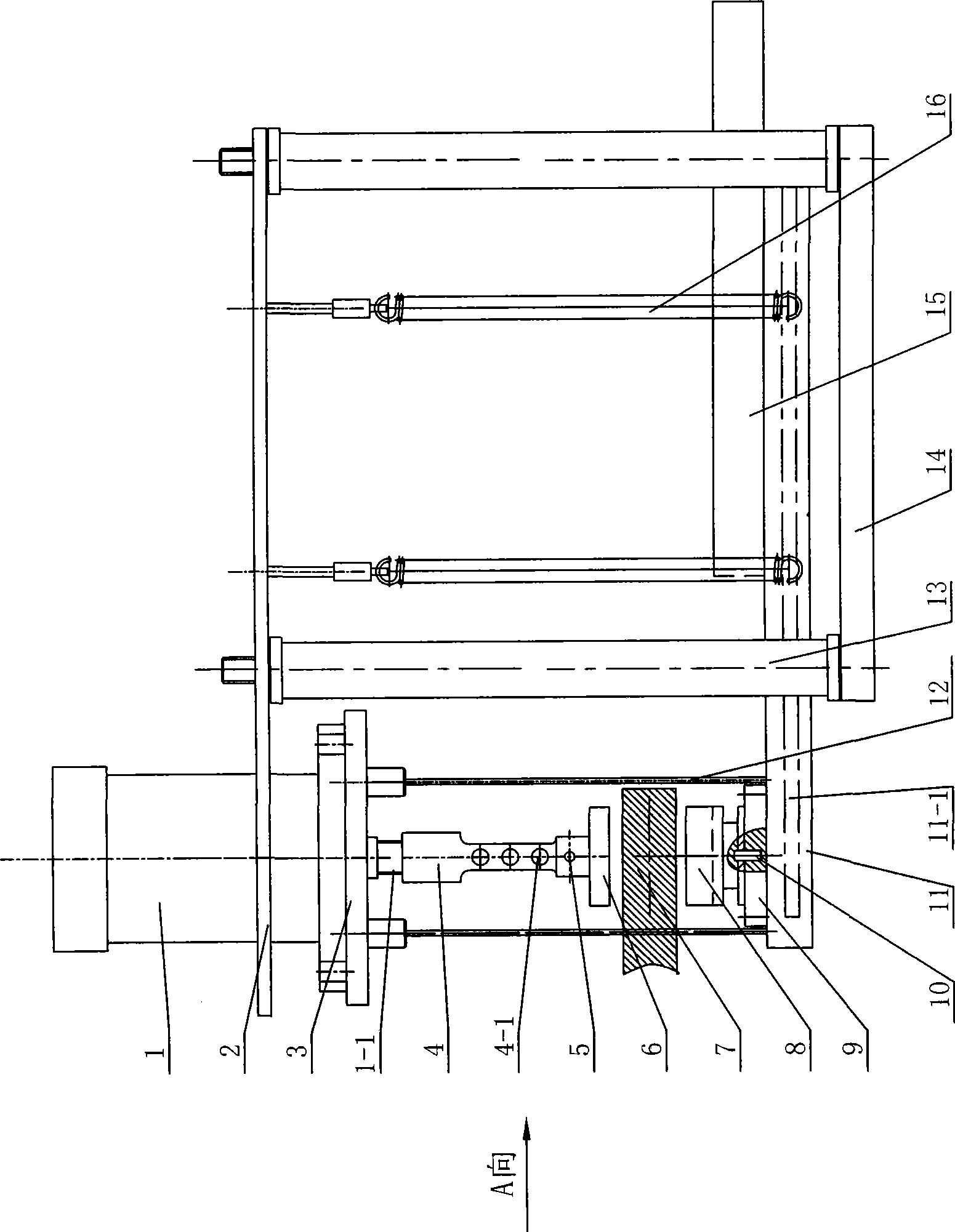
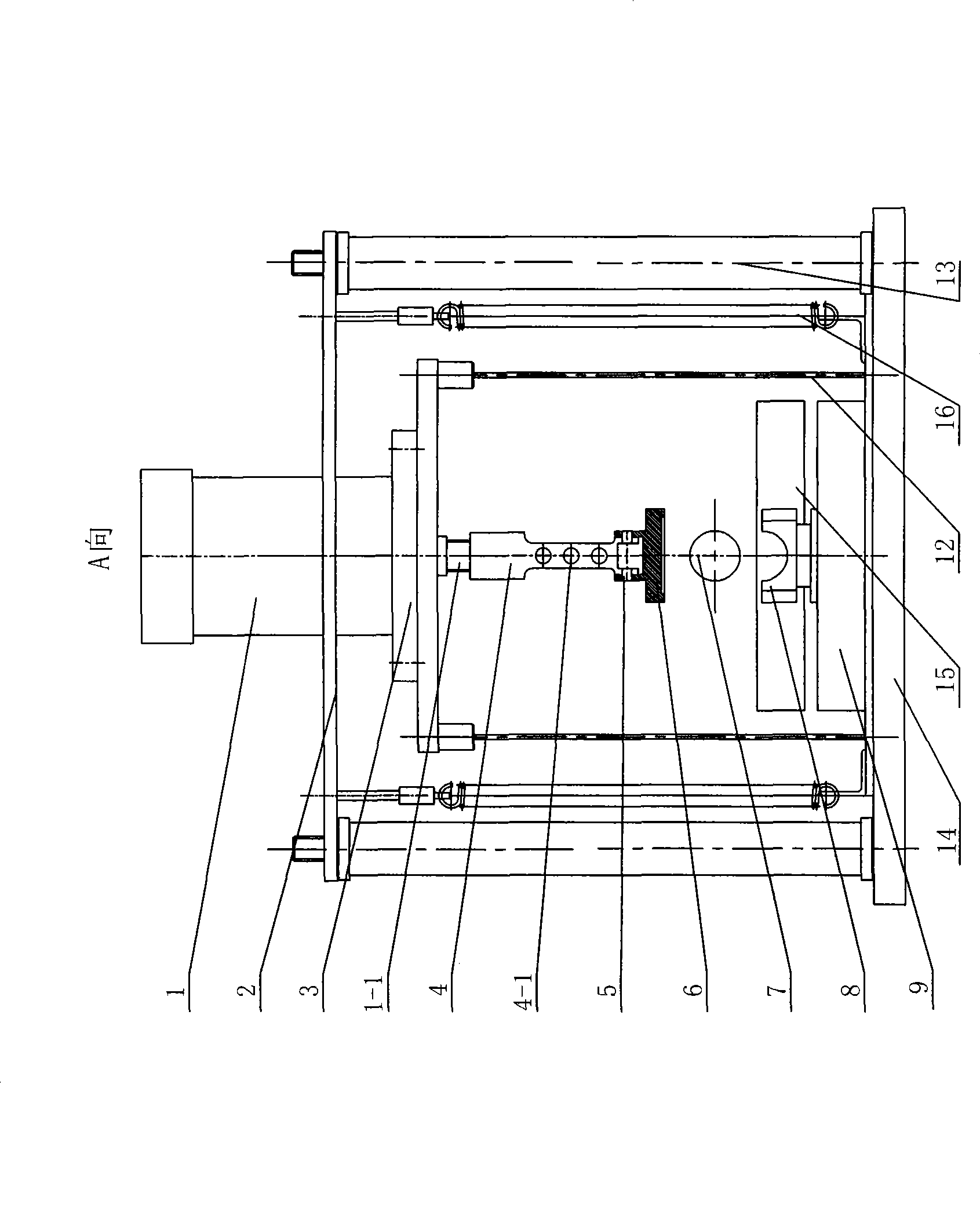
[0010] See figure 1 , 2 As shown, the electrode clamping and positioning device for bar heating of the present invention includes a connecting plate 2, a floating frame, a flexible conductive plate 15 and a floating clamping mechanism. Two sets of electrode clamping and positioning devices of the present invention are installed on the assembly line , Each set of electrode clamping and positioning devices is set on both sides of the bar work, and the distance between the two sets of electrode clamping and positioning devices can be adjusted according to the length of the bar workpiece, which can be used for different sizes and types of bar workpieces.

[0011] See figure 1 , 2 Shown, the floating frame of the present invention comprises conductive seat 11 and more than two extension springs 16, and this extension spring 16 can adopt 2-4 and be arranged on the periphery of connecting plate 2 and conductive seat 11, the extension spring 16 The upper end is insulated and connec...


PUM


Abstract

The invention relates to an electrode clamping and positioning device for bar heating, which comprises a connecting plate, a floating machine frame, a flexible current-conducting plate and a floating clamping mechanism, wherein the floating machine frame comprises a current-conducting seat and a tension spring, one end of the tension spring is in insulated connection with the connecting plate, the other end of the tension spring is connected with the current-conducting seat, and the flexible current-conducting plate is arranged on the current-conducting seat and extends to the front part of the current-conducting seat; and the floating clamping mechanism comprises an elastic supporting rod, an oil cylinder seat, an electrode, a pressure plate and an air cylinder, wherein two ends of the elastic supporting rod are arranged on the current-conducting seat and an air cylinder seat respectively, the air cylinder is arranged on the air cylinder seat, the piston rod of the air cylinder is connected with a radiating rod, the pressure plate is connected with the radiating rod through a horizontal shaft pin, the electrode of which the top is provided with a cambered surface is arranged on the current-conducting seat through a vertical rotating pin, and a distance for mounting a workpiece is reserved between the pressure plate and the electrode. The device can automatically adjust clamping positions according to the mounting surface of a bar workpiece, allows both ends of the bar workpiece to contact the electrode, and is high in loading and clamping efficiency, convenient in maintenance and suitable to be used on an automatic production line for large-scale production.

Description

technical field [0001] The invention relates to an electrode clamping and positioning device for bar heating, belonging to the technical field of bar heat treatment. Background technique [0002] When the two ends of the long metal bar are connected with low voltage and high current, the resistance of the metal material of the metal bar itself is used to heat the metal bar to above 1000°C within a few minutes. This is a new type of fast heating with energy saving and high efficiency. The method has been widely used for rapid heating of bars. However, since the heated metal bar is usually a formed bar, the formed bar is usually a multi-bending workpiece in three-dimensional space, and there are even dozens of bending sections at different angles in three-dimensional space, especially in bending During the forming process, it is not easy to maintain the same spatial position at both ends of the bar workpiece. If electrode heating is used, the positioning positions of the two ...

Claims


Application Information

Patent Timeline
Patent Type & Authority Applications(China)
IPC IPC(8): C21D1/34C21D9/52
Inventor 贺永华郑建军何海庆
Owner 江苏南汽常随汽车零部件有限公司
Why Eureka
Try Eureka