

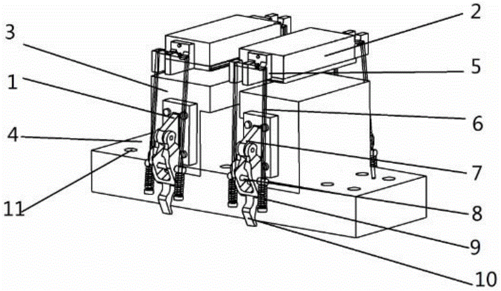
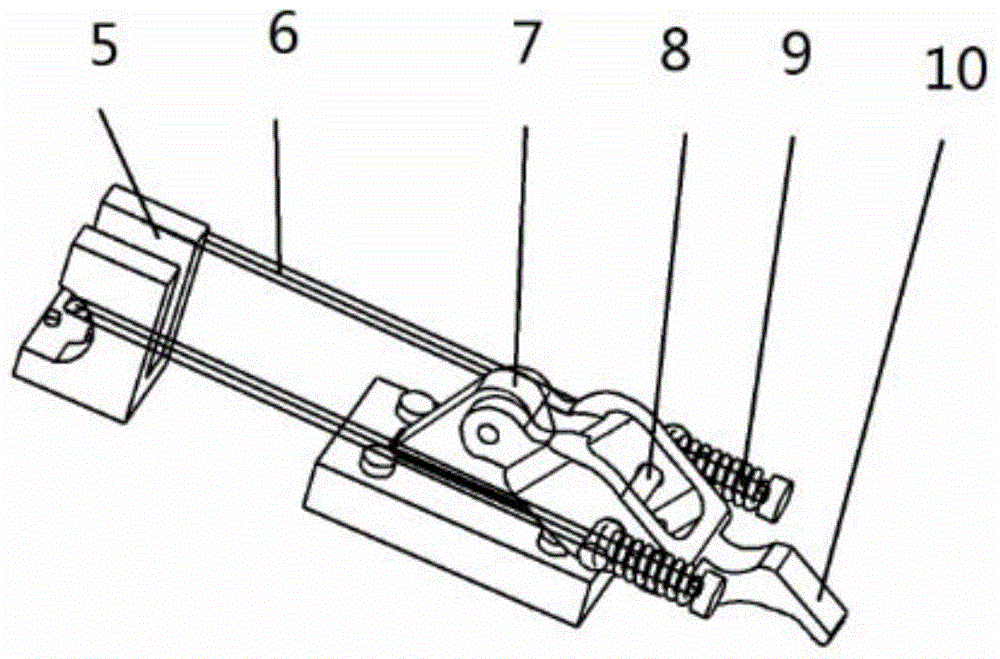
Plate workpiece welding fixture
A welding jig and workpiece clamping technology, applied in the direction of manufacturing tools, welding equipment, auxiliary welding equipment, etc., can solve the problems of the workpiece that has been processed or the surface to be processed, reduce the machining accuracy of the workpiece, and low production efficiency. Improve production efficiency and facilitate processing
- Summary
- Abstract
- Description
- Claims
- Application Information
AI Technical Summary
Problems solved by technology
Method used
Image

Examples
Embodiment
[0029] Select 45# and 40Cr two plates of 100×50×5mm for the workpiece, place the two plates between the left and right pressing positioning blocks 2 and the load-bearing device 3, and adjust the relative position of the load-bearing device 3 on the base 4 , so that the areas to be welded of the two plates meet. Pull down the four locking buttons 1 switch in the device to position and clamp the workpiece. Since the lower end surface of the pressing positioning block 2 has a layer of elastic rubber pad in contact with the workpiece, it avoids the workpiece being processed or has been processed. Cause damage such as indentation. Unclamp locking button 1 after welding and just can take out workpiece, carry out the welding of next workpiece. The whole processing process is fast and simple, the workpiece positioning is convenient, and a large number of workpieces can be processed.
[0030] In summary, the present invention can clamp plate workpieces of different sizes, thereby fac...
PUM
 Abstract
Description
Claims
Application Information