Thin-wall gear ring self-centering tensioning installation fixture

A technology for installing fixtures and thin-walled ring gears, which is used in measuring devices, manufacturing tools, workpiece clamping devices, etc., and can solve the problems that affect the processing quality of thin-walled ring gears, thin-walled ring gears are prone to deformation, and ring gear deformation detection errors and other problems to improve the clamping efficiency and detection accuracy, avoid concentric alignment steps, and ensure the effect of neutrality

Inactive Publication Date: 2015-05-06
XI AN JIAOTONG UNIV
View PDF4 Cites 12 Cited by
  • Summary
  • Abstract
  • Description
  • Claims
  • Application Information

AI Technical Summary

Problems solved by technology

[0003] At present, in the inspection process of thin-walled ring gears, the most commonly used clamping method is to use multi-jaw chucks for clamping, but due to the particularity of its structure, thin-walled ring gears are prone to deformation during the clamping process, and After the clamping on the multi-jaw chuck is completed, it is necessary to perform concentric and horizontal alignment on the measuring equipment. The measurement and clamping process is cumbersome and inefficient, and the deformation of the ring gear will increase the detection error, which will affect the thin-walled teeth. The processing quality of the circle

Method used


Image

  • Thin-wall gear ring self-centering tensioning installation fixture
  • Thin-wall gear ring self-centering tensioning installation fixture
  • Thin-wall gear ring self-centering tensioning installation fixture

Examples


Embodiment

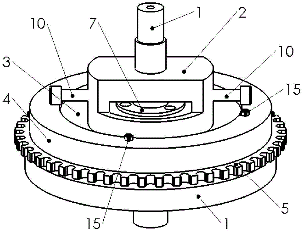
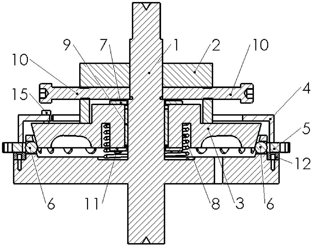
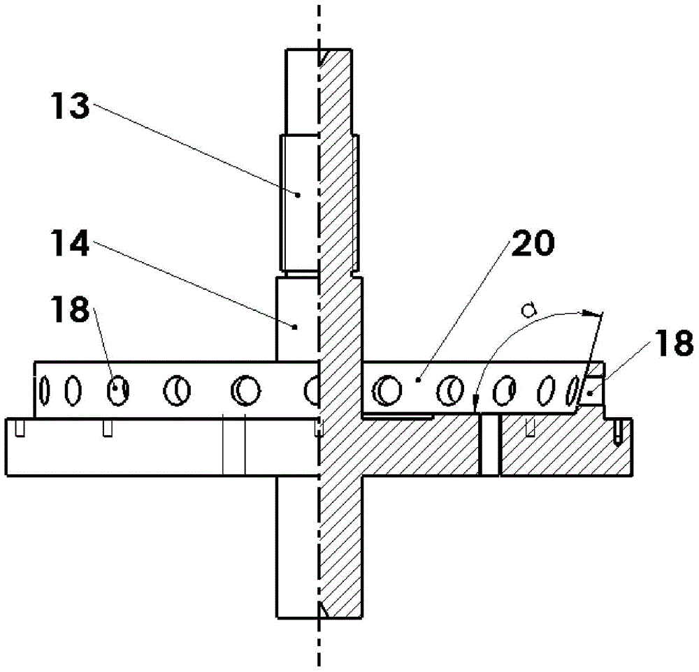
[0036] A self-centering tensioning installation fixture for thin-walled ring gear, see figure 1 , including mandrel base plate 1, compression plate 3, pressure ring 4, compression nut 2, dense ball bearing 9, upper cover 7, lower cover 11, tensioning steel ball 6, ring washer 12, top tight Bolt 10, spring 8, the pressure plate 3 is set on the mandrel base plate 1 through the spring 8, and the dense ball bearing 9 is set between the mandrel precision shaft section 14 on the mandrel base plate 1 and the pressure plate 3 , the upper cover 7 and the lower cover 11 are placed on the compression plate 3, the pressure ring 4 is set on the compression plate 3 and pressed against the thin-walled ring gear under test, the compression nut 2 passes through the thread and the mandrel The mandrel threaded shaft section 13 on the base plate 1 is connected and pressed on the pressure plate 3, the ring washer 12 is arranged on the mandrel base plate 1, and is used to support the thin-walled ri...


PUM


Abstract

The invention provides a thin-wall gear ring self-centering tensioning installation fixture. The thin-wall gear ring self-centering tensioning installation fixture comprises a spindle basic disc, a compression disc, a compression nut, a spring and a plurality of tensioning steel balls. The compression nut compresses the compression disc, the compression disc compresses the tensioning steel balls arranged in radial through holes in an annular wall, therefore, the purpose of tightening a thin-wall gear ring from inside to outside is achieved, and radial location of the gear ring is completed. In the process of clamping, the tensioning steel balls evenly distributed on the spindle basic disc are simultaneously stressed, the thin-wall gear ring can receive outward tensioning force evenly, and therefore deformation of the thin-wall gear ring is effectively restrained; meanwhile, the centering performance of the thin-wall gear ring on measurement equipment is guaranteed. The thin-wall gear ring self-centering tensioning installation fixture effectively reduces deformation of the thin-wall gear ring in the process of clamping, eliminates the steps of concentric centering on the measurement equipment after clamping is completed, and improves clamping efficiency and detection accuracy.

Description

technical field [0001] The invention belongs to the field of precision measurement, and in particular relates to a self-centering tensioning installation fixture for a thin-walled ring gear. Background technique [0002] With the continuous development of the machinery manufacturing industry, the precision requirements of the transmission system are getting higher and higher, and the gear is an important part of the transmission system, and its machining accuracy has a great impact on the transmission system. The actual detection results of the gear machining accuracy are often used as It is an important basis for improving the gear processing technology, so the requirements for the actual detection accuracy of the gear are getting higher and higher. [0003] At present, in the inspection process of thin-walled ring gears, the most commonly used clamping method is to use multi-jaw chucks for clamping, but due to the particularity of its structure, thin-walled ring gears are ...

Claims


Application Information

Patent Timeline
Patent Type & Authority Applications(China)
IPC IPC(8): B25B11/00G01M13/02
CPCB25B11/00G01M13/021
Inventor 刘阳鹏丁建军王丰东李兵蒋庄德
Owner XI AN JIAOTONG UNIV
Why Eureka
Try Eureka