Radiation detection aircraft

A technology for nuclear detectors and aircraft, applied in the field of nuclear radiation detection, can solve problems such as poor emergency handling capabilities of robots, and achieve the effect of improving emergency handling capabilities

Inactive Publication Date: 2014-05-28
TECHN PHYSICS INST HEILONGJIANG ACADOF SCI
View PDF6 Cites 30 Cited by
  • Summary
  • Abstract
  • Description
  • Claims
  • Application Information

AI Technical Summary

Problems solved by technology

[0004] The purpose of the present invention is to solve the problem of poor emergency handling capabilities of existing robots used for nuclear radiation detection, and to provide a nuclear radiation detection aircraft

Method used


Image

  • Radiation detection aircraft
  • Radiation detection aircraft
  • Radiation detection aircraft

Examples


specific Embodiment approach 1

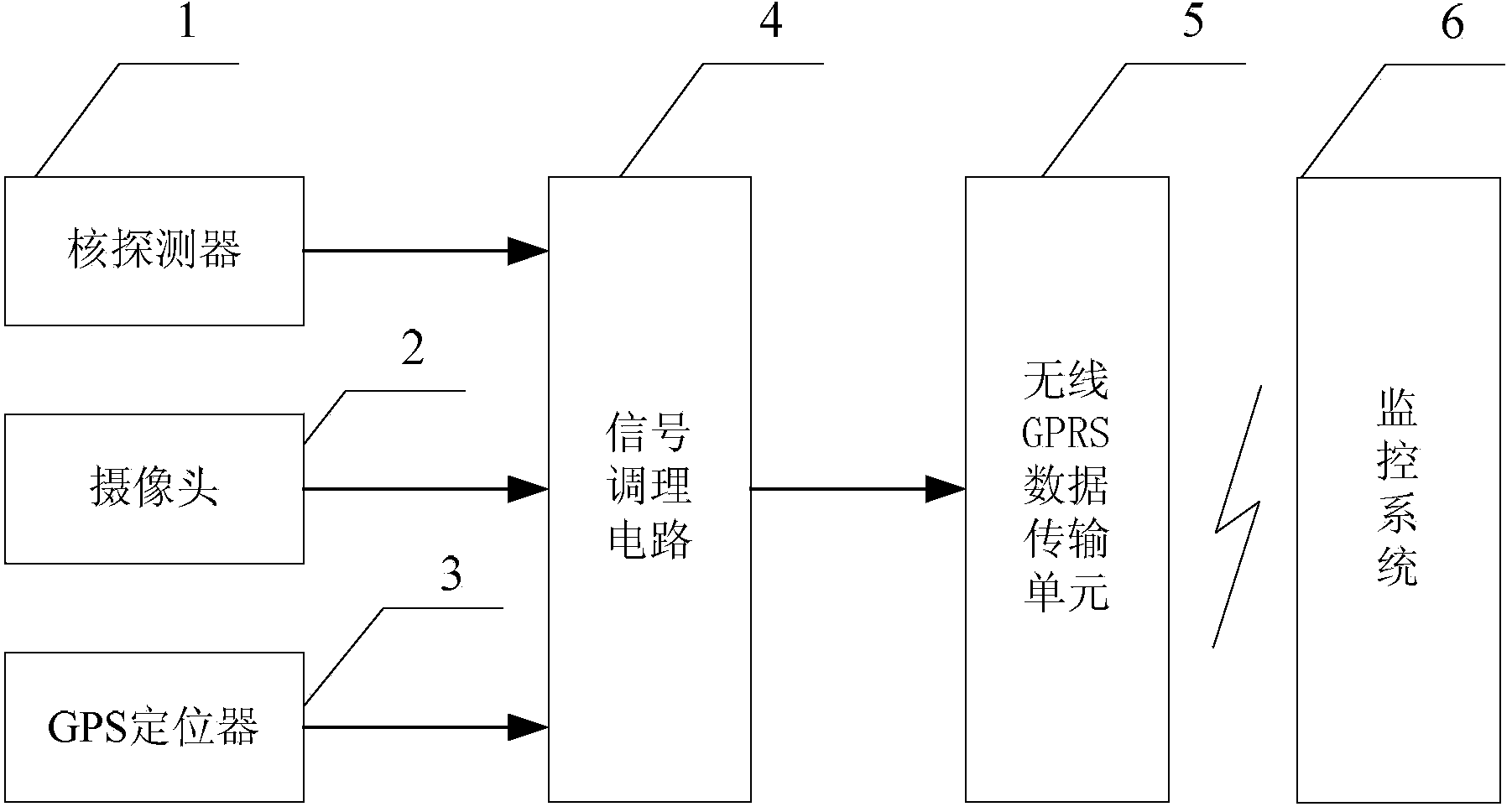
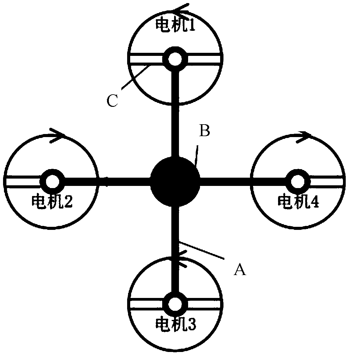
[0016] Specific implementation mode one: the following combination figure 1 Illustrate the present embodiment, the nuclear radiation detection aircraft described in the present embodiment, it comprises quadrotor aircraft carrier, it also comprises nuclear detector 1, camera 2, GPS locator 3, signal conditioning circuit 4 and wireless GPRS data transmission unit 5,

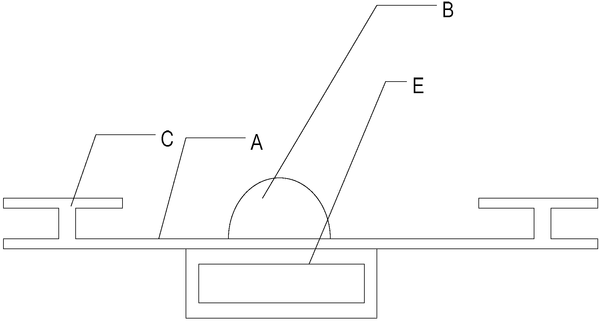
[0017] The camera 2 is arranged on the flight front-end housing of the quadrotor aircraft carrier, the nuclear detector 1 is mounted on the lower end of the housing of the quadrotor aircraft carrier, and the GPS locator 3 is used to realize the positioning of the flight position of the quadrotor aircraft carrier,

[0018] The detection signal output end of the nuclear detector 1 is connected to the detection signal input end of the signal conditioning circuit 4, the imaging signal output end of the camera 2 is connected to the imaging signal input end of the signal conditioning circuit 4, and the positioning signal ...

specific Embodiment approach 2

[0019] Embodiment 2: This embodiment further explains Embodiment 1. The Geiger counter tube of the nuclear detector 1 described in this embodiment is powered by a high-voltage module, and the high-voltage module is covered with a lightweight metal mesh.

[0020] Since the high-voltage module will form a strong electromagnetic field around it, which will affect the radio signal, in order to solve the interference of the high-voltage module on the radio signal, it is necessary to shield the electromagnetic field formed when the high-voltage module is working to prevent it from affecting the wireless control signal. interference, affecting the flight control of the detection device. At the same time, keep the high-voltage module and the communication module as far away as possible.

specific Embodiment approach 3

[0021] Specific implementation mode three: the following combination figure 1 Describe this embodiment, this embodiment will further explain Embodiment 1 or 2, this embodiment also includes a monitoring system 6, the wireless GPRS receiving unit of the monitoring system 6 and the wireless GPRS data transmission unit 5 transmit signals by wireless.

[0022] The monitoring system 6 can be used to monitor the positioning and tracking of the nuclear radiation detection aircraft, and analyze the radiation distribution in the area where it is located. The monitoring system 6 and the wireless GPRS data transmission unit 5 can perform two-way communication, and the detected dose data can be sent to the monitoring system 6 of the emergency command center through wireless transmission, and the monitoring system 6 can also send control instructions to the nuclear detection system through a wireless network. Device 1.

[0023] When more functional modules are added, the load on the radia...


PUM


Abstract

The invention discloses a radiation detection aircraft, which belongs to the technical field of radiation detection, and aims at solving the problem that an existing robot for nuclear radiation detection is poor in capacity for emergency management. A camera is arranged on a flying front-end shell of a four-rotor aircraft carrier; a nuclear detector is mounted at the lower end of the shell of the four-rotor aircraft carrier; a global position system (GPS) locator is used for locating the flying position of the four-rotor aircraft carrier; a detected signal output end of the nuclear detector is connected with a detected signal input end of a signal conditioning circuit; an imaging signal output end of the camera is connected with an imaging signal input end of the signal conditioning circuit; a locating signal output end of the GPS locator is connected with a locating signal input end of the signal conditioning circuit; a conditioning signal output by the signal conditioning circuit is transmitted through a wireless general packet radio service (GPRS) data transmission unit. The radiation detection aircraft is applied to nuclear radiation detection.

Description

technical field [0001] The invention relates to a nuclear radiation detection aircraft and belongs to the technical field of nuclear radiation detection. Background technique [0002] The application of radioactive sources has both advantages and disadvantages. On the one hand, it can serve human beings, and on the other hand, it will cause ecological pollution and public harm. In recent years, nuclear leakage incidents, loss and theft of radioactive sources have occurred frequently. How to minimize the loss and harm caused by radioactive source accidents is an urgent problem in front of us. [0003] At present, most of the robots for emergency response to radioactive source accidents adopt wheel-type, crawler-type or crawler-type structural designs. This type of robot is large in size and extremely poor in flexibility. It is greatly affected by the terrain of the accident site and ground obstacles during its travel. , it is easy to be stuck and cannot be retracted; due to ...

Claims


Application Information

Patent Timeline
Patent Type & Authority Applications(China)
IPC IPC(8): G01T1/00G01T1/16B64C27/08
Inventor 侯跃新杨斌李岩肖丹李钢
Owner TECHN PHYSICS INST HEILONGJIANG ACADOF SCI
Why Eureka
Try Eureka