Balers and baling methods
A technology of baler and rotary drive mechanism, applied in the field of baler and baler, to achieve the effect of high density and high plunger force
- Summary
- Abstract
- Description
- Claims
- Application Information
AI Technical Summary
Problems solved by technology
Method used
Image
Examples
Embodiment Construction
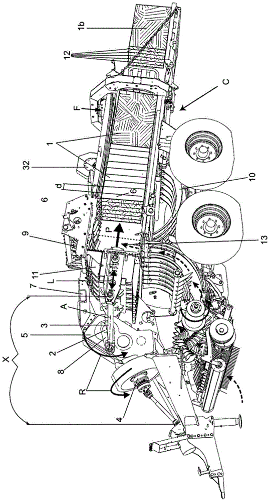
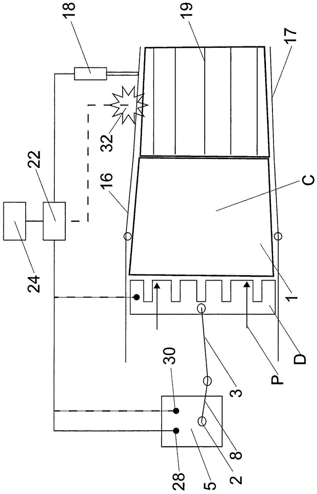
[0034]figure 1 The baling machine or baler shown in includes a baling chamber C and a plunger D that can be driven into the baling chamber C in a reciprocating manner. The baler also includes a pick-up mechanism M for picking up cut bale material, such as grass and straw, from the ground, a feed mechanism N for feeding the bale material into the baling chamber C, and a mechanism for feeding the drive from the tractor ( Not shown) drive output to drive train X for plunger D. These components are all conventional and may be as described, for example, in US Patents 4,074,623 and 4,142,746. The tying machine also includes a binding device E for binding with a binding hemp rope. The binding means may for example be as described in US 4074623 .
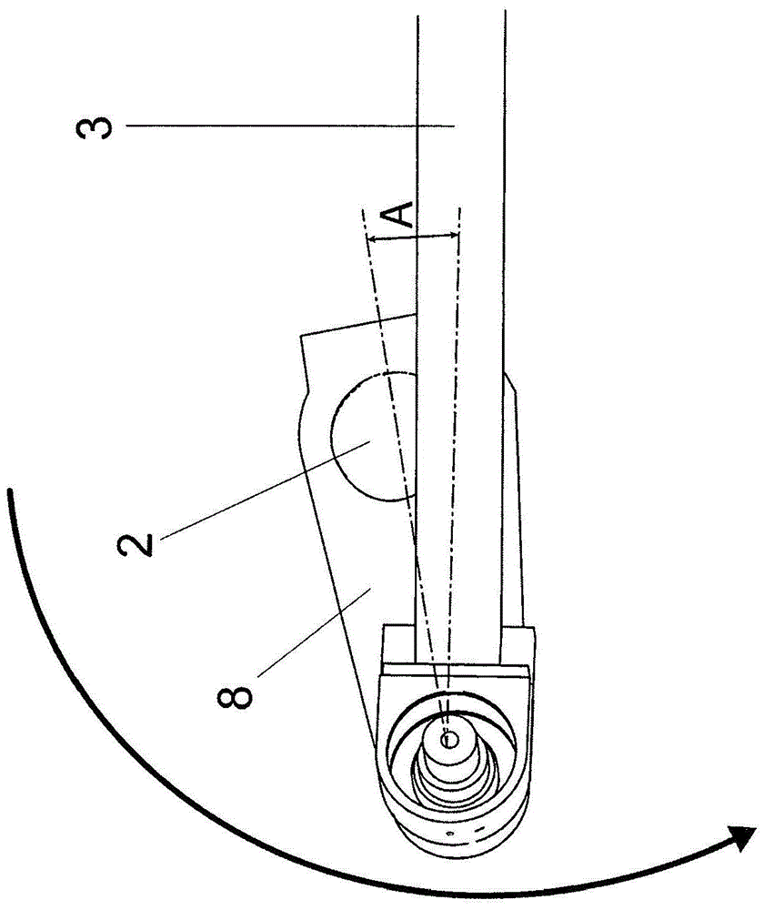
[0035] The baling chamber C comprises an open-ended bale-forming channel through which the bale material 1 is pushed by the reciprocating plunger D. In this example, the plunger D is driven from the rotary drive shaft 2 via the crank 8 a...
PUM
 Abstract
Description
Claims
Application Information
 - R&D
- Intellectual Property
- Life Sciences
- Materials
- Tech Scout
- Unparalleled Data Quality
- Higher Quality Content
- 60% Fewer Hallucinations
Browse by: Latest US Patents, China's latest patents, Technical Efficacy Thesaurus, Application Domain, Technology Topic, Popular Technical Reports.
© 2025 PatSnap. All rights reserved.Legal|Privacy policy|Modern Slavery Act Transparency Statement|Sitemap|About US| Contact US: help@patsnap.com


