Eureka AIR delivers breakthrough ideas for toughest innovation challenges, trusted by R&D personnel around the world.

Method for driving print unit

A printing unit and driving motor technology, applied in printing, printing machines, general parts of printing machinery, etc., can solve the problems of power design asymmetry, motor or regulator overload, and other problems, so as to achieve full and good operation and avoid over The effect of the design

Inactive Publication Date: 2006-05-10
KOENIG & BAUER AG
View PDF3 Cites 0 Cited by
  • Summary
  • Abstract
  • Description
  • Claims
  • Application Information

AI Technical Summary

Problems solved by technology

Due to significantly different power flows will lead to power design asymmetry, will lead to different power or even cause overloading of the motor or regulator depending on the conditions and operating mode respectively

Method used


Image

  • Method for driving print unit
  • Method for driving print unit
  • Method for driving print unit

Examples


Embodiment Construction

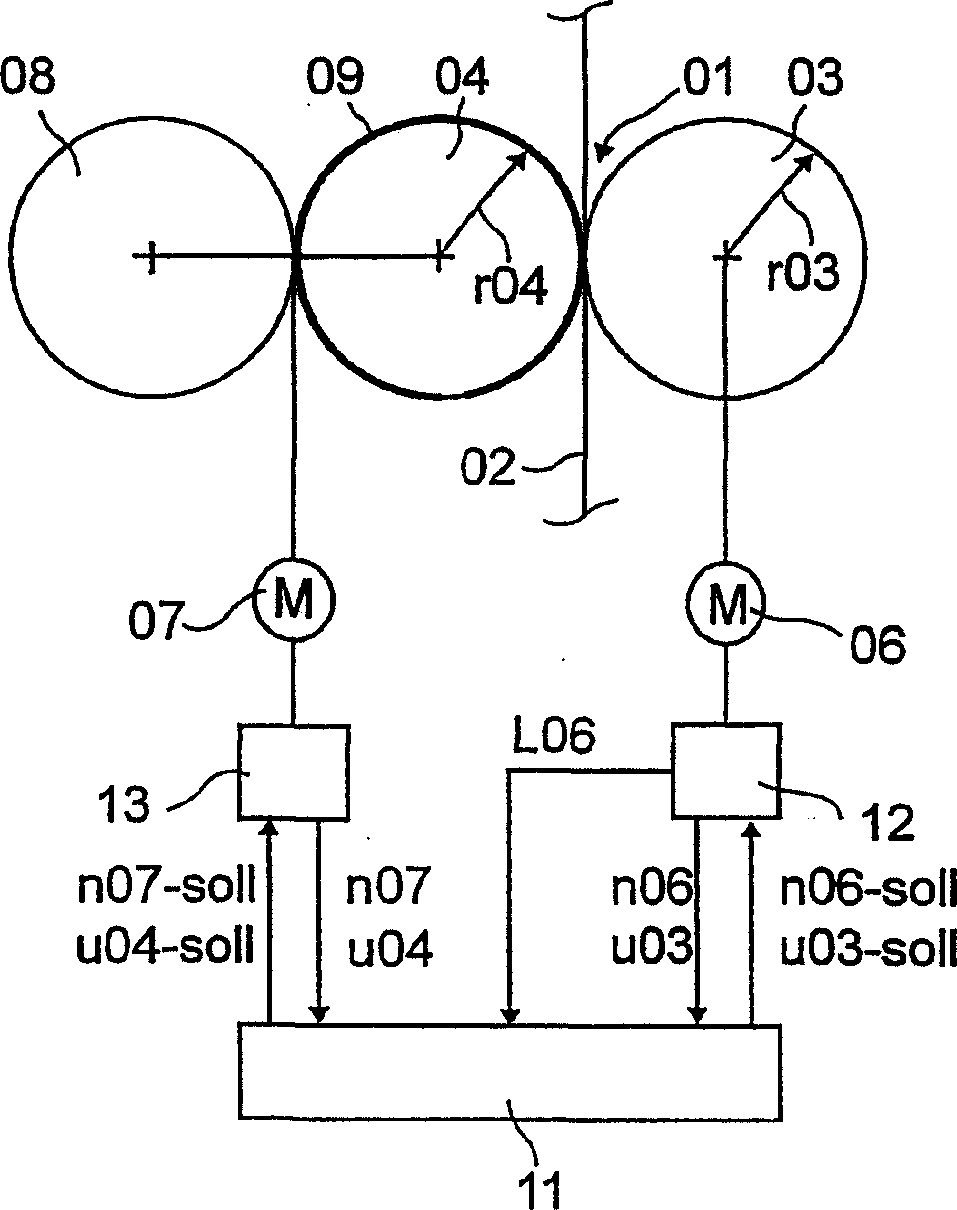
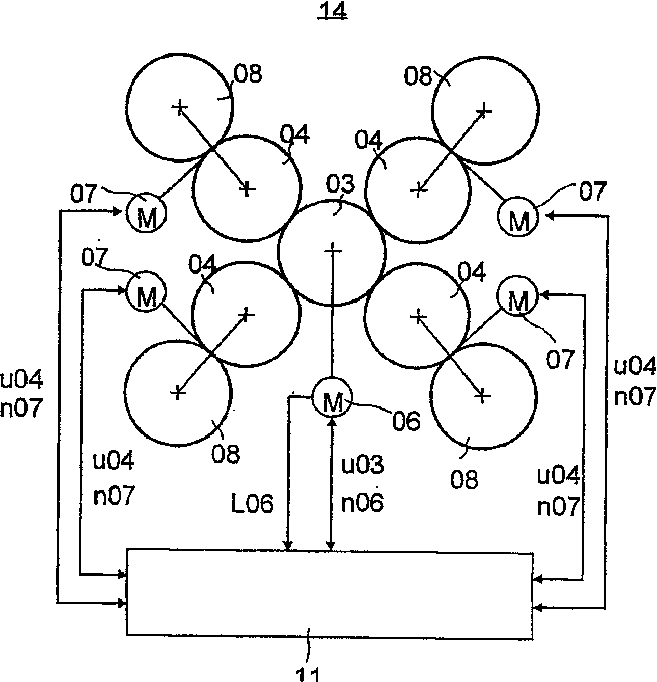
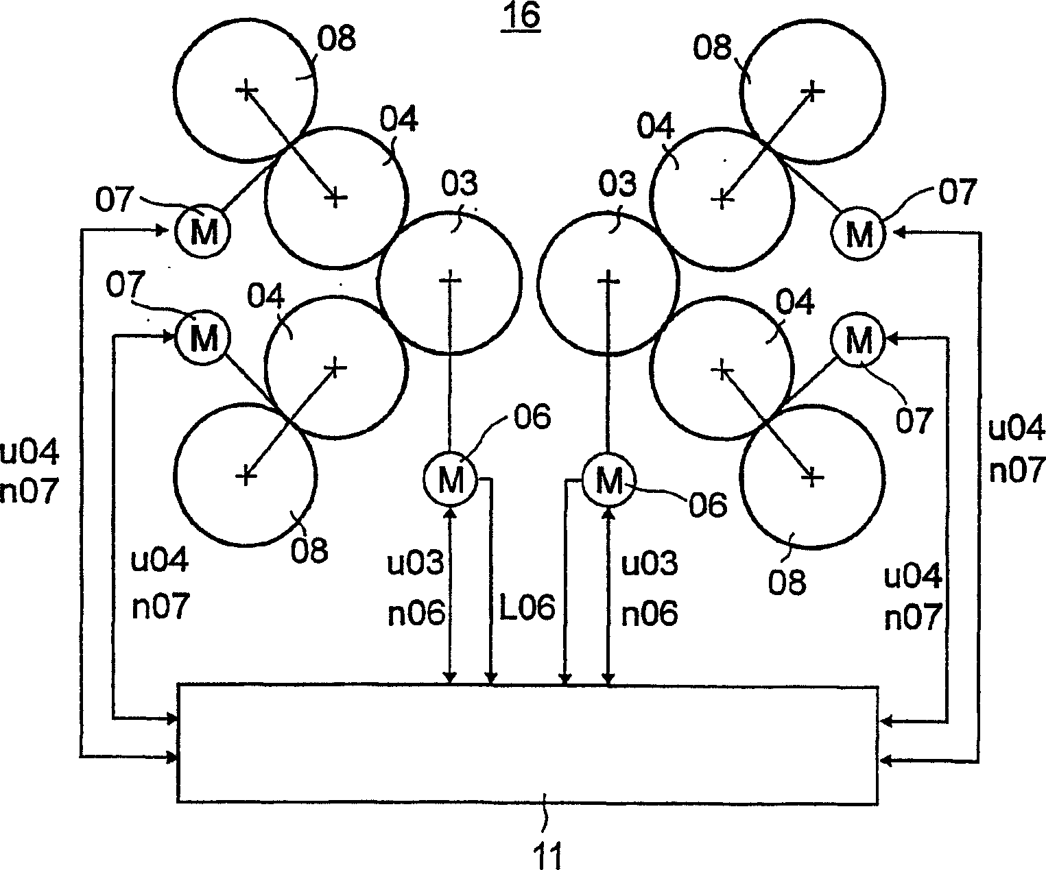
[0022] The rotary printing press has a printing point 01 with two rollers on a belt, such as a printing material belt, especially a paper belt 02, which are press-fitted on each other. The roller is, for example, without a roller and uses its mutually rolling shell surfaces to form a friction transmission device. The first cylinder is an impression cylinder 03, such as a steel cylinder and directly or indirectly through a drive motor 06, but independent of the second cylinder, such as a transfer cylinder 04 or a copper-zinc plate cylinder for high-pressure or flexographic printing. driven.

[0023] For example, the second roller as the transfer roller 04 is also directly or indirectly driven, for example, by a transmission device not shown in the figure, such as a gear, a toothed belt, or a friction transmission device using the second drive motor 07. The transfer cylinder 04 can be driven separately or together with a third cylinder cooperating with the transfer cylinder, such as...


PUM


Abstract

The present invention involves a method used to drive the printing unit. The printing unit has at least one printed drum and one transparent roller that forms a printing point with a printed drum.The speed is driven by two commonly matched and stress -contact rollers and transferred drums.The advantage of the present invention is that the full and good operation of the pressure roller can be achieved, which is largely not subject to the number of printing points, the hardness of the lining, and / or the lining of the printing point that is not compressed and / or is being played.Types and influence of manufacturers.

Description

Technical field [0001] The invention relates to a method of driving a printing unit. Background technique [0002] For example, when a separate driving device is used to drive a roller or a roller group in a satellite printing unit, there will be an execution deviation determined by the process between the roller pairs. The deviation depends on the combined pressure, the number of printing points in the working state, the hardness of the lining, the type and manufacturer of the lining, whether the friction transmission device has a roller, the radius of the roller and the radius ratio of the friction transmission device. [0003] This point, under the prevailing and alternate conditions at present, will result in a significantly different power flow between the drums or groups of drums. Obviously different power flows will lead to asymmetry in power design, which will lead to different powers or even overloads of motors or regulators due to conditions and working methods. [0004...

Claims


Application Information

Patent Timeline
Patent Type & Authority Patents(China)
IPC IPC(8): B41F13/004B41F33/00
CPCB41F13/0045B41P2213/734
Inventor 艾哈德·赫伯特·格勒克尔贝尔恩德·库尔特·马祖赫
Owner KOENIG & BAUER AG
Why Eureka
Eureka Blog
Learn More