Flexible clamping device and clamping method based on magnetorheological fluid

A flexible clamping, magnetorheological fluid technology, applied in the direction of chucks, manipulators, manufacturing tools, etc., can solve the problems of unsuitability for large-scale industrial production, adjustment of contact stiffness, unstable clamping, etc., and achieve stable and effective clamping. The effect of holding and carrying

Inactive Publication Date: 2014-06-04
CHONGQING INST OF GREEN & INTELLIGENT TECH CHINESE ACADEMY OF SCI
View PDF8 Cites 28 Cited by
  • Summary
  • Abstract
  • Description
  • Claims
  • Application Information

AI Technical Summary

Problems solved by technology

However, the existing methods have the following shortcomings that cannot be overcome: (1) The contact stiffness cannot be adjusted arbitrarily according to the actual requirements and the rigidity of the clamped object, thus limiting its application range; (2) The existing technology uses surface material elasticity Deformation to achieve the purpose of simulating the shape of the clamped object
Due to the unbalanced pressure on the outer surface of the clamped object, the clamped object may be damaged and clamped unstable; (3) the deformation of the compliant surface used in the prior art is caused by extrusion, After reaching the deformation to adapt to the shape of the surface of the clamped object, if it is disturbed by an external force, the shape will still change, and the clamped object cannot be fixed very firmly. (4) In the current industrial production, mechanical clamping in the existing clamping technology The method has the disadvantages that the clamping force can be adjusted low, and the workpiece is often damaged or the clamping is unstable; (5) the vacuum adsorption clamping method is not suitable for large-scale industrial production due to its high cost
To sum up, there is still a lack of an economical, convenient and flexible clamping technology that can be applied to high-precision non-destructive engineering operations.

Method used


Image

  • Flexible clamping device and clamping method based on magnetorheological fluid
  • Flexible clamping device and clamping method based on magnetorheological fluid

Examples


Embodiment Construction

[0024] Hereinafter, preferred embodiments of the present invention will be described in detail with reference to the accompanying drawings. It should be understood that the preferred embodiments are only for illustrating the present invention, but not for limiting the protection scope of the present invention.

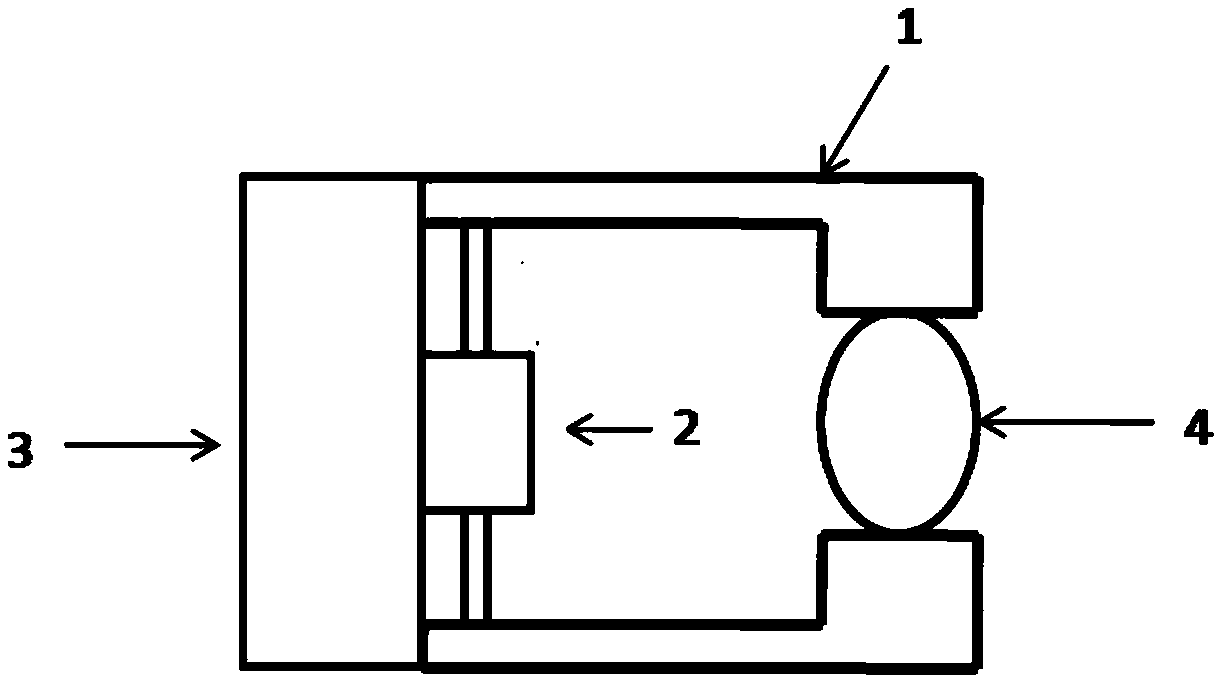
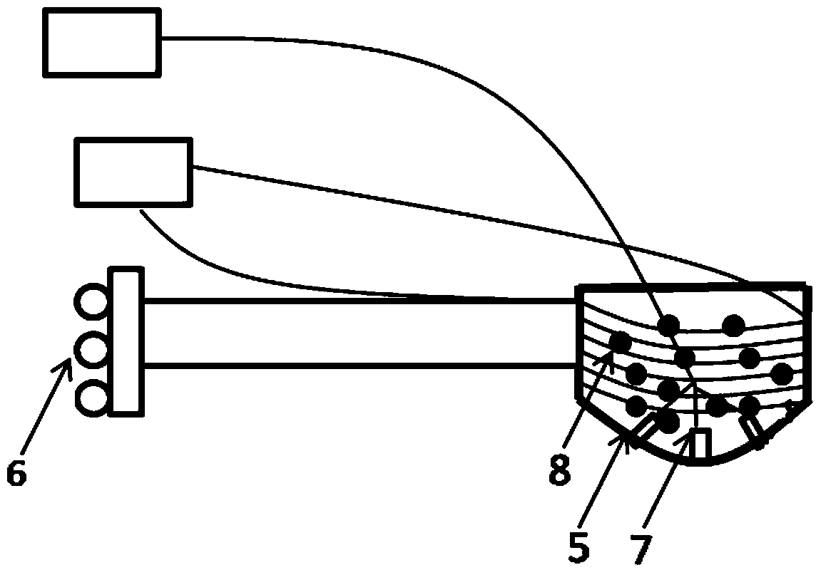
[0025] As shown in the figure, a flexible clamping device based on magnetorheological fluid includes a clamping base 3 and a clamping arm 1 arranged on the clamping base. 4, the clamping end is provided with a flexible clamping body with a flexible clamping surface, the flexible clamping body is provided with a magneto-rheological fluid 8, and the flexible clamping body is also provided with a A variable magnetic field generator that generates a variable magnetic field to a magnetorheological fluid.

[0026] In this embodiment, different from the traditional mechanical clamping method, the rheological adjustability of the magnetorheological fluid is used to change the...


PUM


Abstract

The invention discloses a flexible clamping device and clamping method based on magnetorheological fluid. The flexible clamping device comprises a clamping base and clamping arms arranged on the clamping base, wherein the clamping arms are provided with clamping ends used for clamping an object, the clamping ends are provided with flexible clamping bodies with clamping surfaces, and the flexible clamping bodies are filled with the magnetorheological fluid and further provided with variable-magnetic-field generators used for generating variable magnetic fields for the magnetorheological fluid. The clamping method is totally different from a traditional mechanical clamping method in clamping principle, and the object is clamped in the manner of changing interface friction coefficients based on the rheological property and adjustability of the magnetorheological fluid; in this way, the object can be stably and effectively clamped and carried, pressure output of the clamping ends will not be additionally increased, and accordingly the whole clamping process can be carried out without causing loss.

Description

technical field [0001] The invention belongs to the field of clamping devices, and in particular relates to a flexible clamping device and a clamping method based on magnetorheological fluid. Background technique [0002] In the robot industry, when clamps and manipulators are used to hold an object with irregular shapes, in order not to damage the object, it is necessary to reduce the contact stress, increase the contact area, and increase the friction. This requires a certain flexibility of the contact surface. This can prevent the clamped object from being pinched and improve the stability of the clamping. The methods currently used mainly include the use of elastic materials as the flexible outer surface, or the clamping method of vacuum adsorption. However, the existing methods have the following shortcomings that cannot be overcome: (1) The contact stiffness cannot be adjusted arbitrarily according to the actual requirements and the rigidity of the clamped object, th...

Claims


Application Information

Patent Timeline
Patent Type & Authority Applications(China)
IPC IPC(8): B25J15/08B25J19/00
Inventor 朱晓强何国田吴姣娇徐泽宇林远长陈希何骥鸣赵健刘永福谷明信
Owner CHONGQING INST OF GREEN & INTELLIGENT TECH CHINESE ACADEMY OF SCI
Why Eureka
Try Eureka