Fan with guiding rib in vent

a technology of guiding ribs and vents, which is applied in the direction of machines/engines, stators, liquid fuel engines, etc., can solve the problems of affecting the air pressure of the fan, the structure of the guiding apparatus is very complicated, and the air pressure damage and efficiency reduction of the fan, so as to reduce the resistance and increase the pressure output

Inactive Publication Date: 2005-01-06
DATECH TECH CO LTD
View PDF13 Cites 19 Cited by
  • Summary
  • Abstract
  • Description
  • Claims
  • Application Information

AI Technical Summary

Benefits of technology

[0009] The main objective of the present invention is to reduce the resistance generated by guiding ribs and to guide the air flow blown from fan blades to further increase pressure output by the fan.

Problems solved by technology

However, since being in a stick shape, when the fan blade blows, the guiding ribs will generate air flow (air pressure) with air resistance, which affects the air pressure of the fan.
Moreover, the cyclone is generated due to interference of the stick-shaped guiding ribs after the air flow generated by the fan blades passes through the guiding ribs, therefore resulting in air pressure damages and efficiency reduction of the fan.
However, since the guiding rib is replaced by others with a shape similar to the rotor blades (there are two blades on the fan, one is rotor blade which is rotatable; the other one is static blade mounted on the frame body), the structure of the guiding apparatus turns out to be very complicated.

Method used


Image

  • Fan with guiding rib in vent
  • Fan with guiding rib in vent
  • Fan with guiding rib in vent

Examples


Embodiment Construction

[0022] The following descriptions of the preferred embodiments are provided to understand the features and the structures of the present invention.

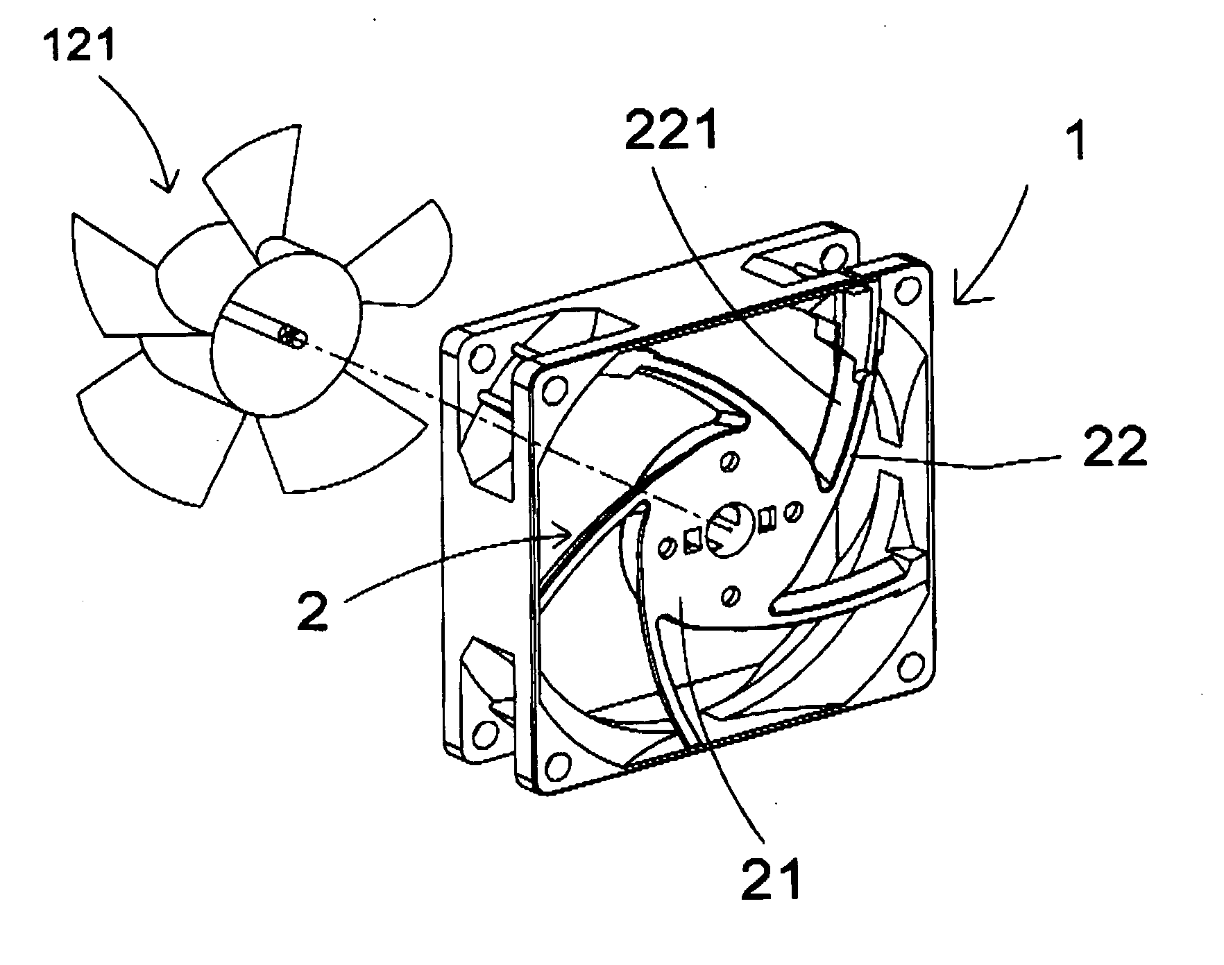
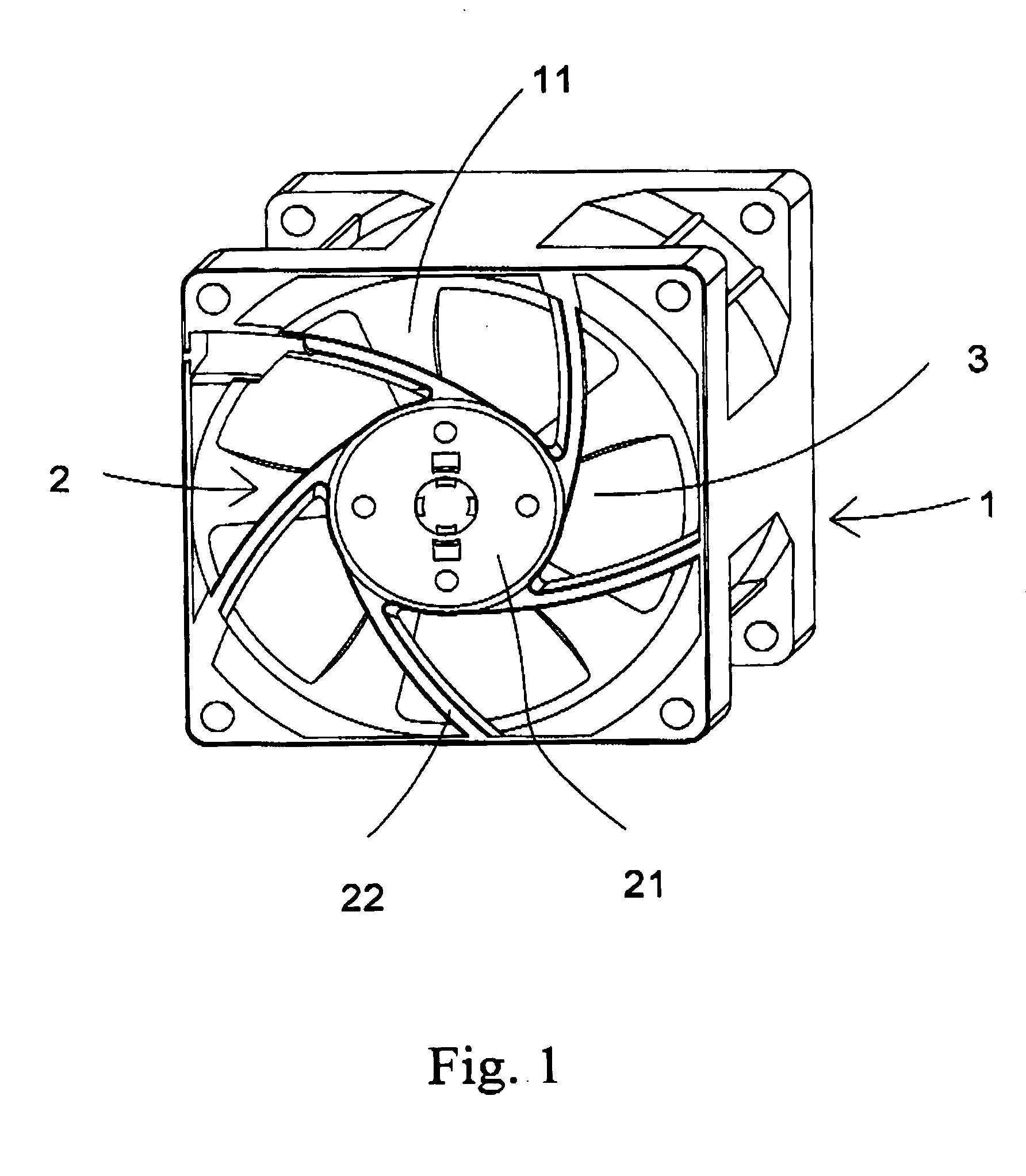
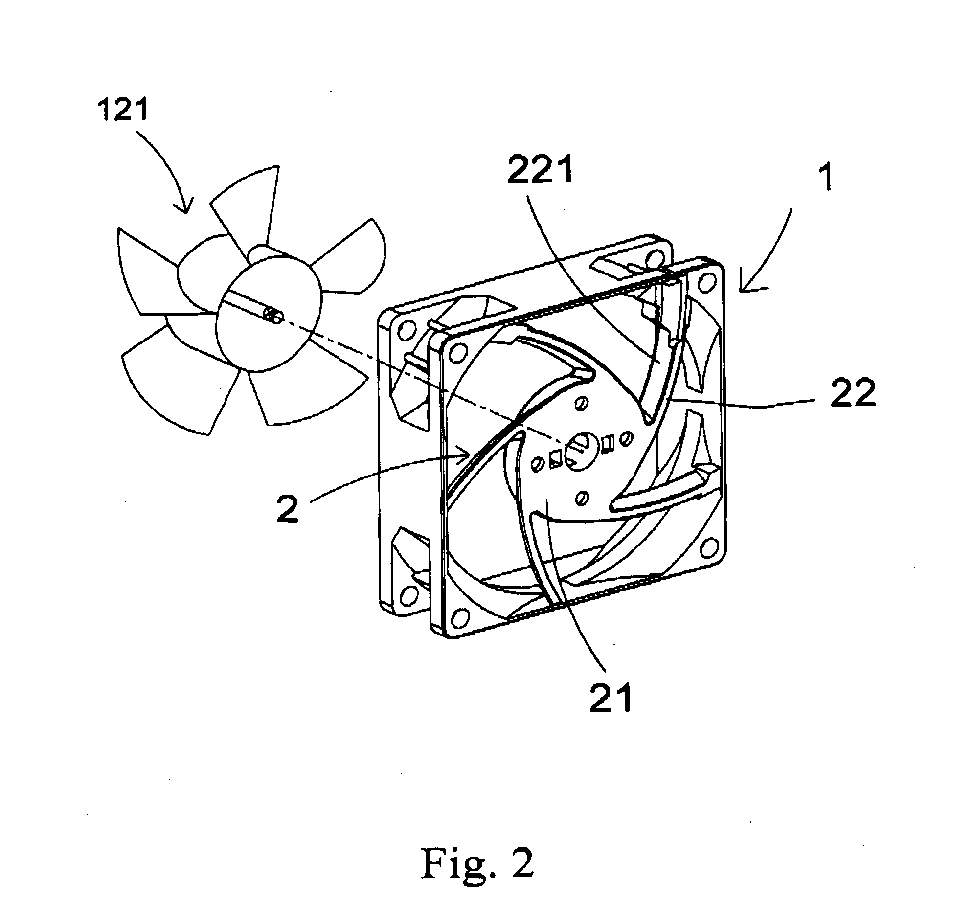
[0023]FIG. 1, FIG. 2, and FIG. 3 are respectively a diagram showing an outward appearance of the present invention, a diagram showing a view in separation configuration of the present invention, and a cross-section diagram of the present invention. As shown in the diagrams, the present invention provides a fan with guide ribs in a vent, comprising a frame body 1 and a supporting part 2. By that, complicated components in the prior art can be simplified, and the resistance generated by the guiding ribs can be reduced as well. Furthermore, the air flow blown from fan blades is guided to further increase pressure output by the fan.

[0024] The frame body 1 mentioned above has a hole 11 in its central portion;

[0025] The support part 2 is composed of a pivot 21 and guiding ribs 22 with outside extension from the pivot 21. Wherein, the pivot 2...


PUM


Abstract

A fan with guiding ribs in a vent comprises a frame body and a supporting part. The supporting part comprises a pivot connecting fan blade and guiding ribs with outside extension, wherein by means of the guiding ribs, the supporting part is disposed on the inner end surface of the frame body and the profile of guiding ribs is to have an inclined plane that gradually shrink from the end surface to fan blades. By the above structure, complicated components in the prior art can be simplified and the resistance generated by the guiding ribs can be reduced as well. Furthermore, the air flow blown from fan blades is guided to further increase pressure output by the fan.

Description

REFERENCE CITED [0001] 1. U.S. Pat. No. 6,244,818 B1FIELD OF THE INVENTION [0002] The present invention relates to a fan with guiding ribs in a vent. More particularly, by the structure, complicated components in the prior art can be simplified and the resistance generated by the guiding ribs can be reduced as well. Furthermore, the air flow blown from fan blades is guided to further increase pressure output by the fan. BACKGROUND OF THE INVENTION [0003] A conventional fan comprises a vent; a supporting part for supporting fan blades to rotate thereof. There are guiding ribs with outside extension from the circumference of the supporting part, connecting to the fan frame body. The guiding rib is in a stick shape for supporting the supporting part to mount on the central portion of the vent. However, since being in a stick shape, when the fan blade blows, the guiding ribs will generate air flow (air pressure) with air resistance, which affects the air pressure of the fan. Moreover, t...

Claims


Application Information

Patent Timeline
Patent Type & Authority Applications(United States)
IPC IPC(8): F03B1/00F04D29/40F04D29/54
CPCF04D29/542
Inventor LI, NIEN-LUNWANG, FU-YINCHOU, YU-HSUN
Owner DATECH TECH CO LTD
Why Eureka
Try Eureka