Shuttling trolley type perpendicular lifting device

A lifting device and trolley-type technology, applied in the direction of lifting devices, etc., can solve the problems of general products without structure, waste of equipment and workshop space, and increase costs, so as to reduce design length and production costs, facilitate maintenance and replacement, and save costs Effect

Inactive Publication Date: 2014-06-04
LUOYANG LIHE MACHINERY
View PDF6 Cites 1 Cited by
  • Summary
  • Abstract
  • Description
  • Claims
  • Application Information

AI Technical Summary

Problems solved by technology

[0004] When working normally, under the action of the power source F, the wheel set 21 of the upper trolley on the upper trolley 20 rolls along the inclined block 22 to realize lifting, and the vertical lifting height changes from the original height H to H+lifting Height H1; however, an additional horizontal displacement S will be generated, that is, the horizontal distance L before lifting becomes the horizontal distance L+S after lifting, and at the same time, the length of the feeder truck will increase from A to A+S. This will cause inconvenience to production
[0005] Specifically, if there is a change in the horizontal displacement of the material truck, on the one hand, it will increase the length of the industrial furnace used with it by a horizontal displacement length, and at the same time, it will increase the length of the factory building by a horizontal displacement length, which will cause the same The equipment supporting the material truck and the space of the factory building are wasted, thereby increasing the cost
On the other hand, the change of the horizontal displacement of the feeding cart will cause friction between the upper surface of the feeding cart and the lower surface of the goods to be loaded, which will damage the lower surface of the parts and affect the quality of the parts. The wear of the upper surface of the feeding cart will also affect the quality of the parts. Appearance of the truck
[0006] This shows that the above-mentioned existing vertical lifting device obviously still has inconvenience and defects in structure and use, and needs to be further improved urgently.
In order to solve the existing problems, the relevant manufacturers have tried their best to find a solution, but no suitable design has been developed for a long time, and the general products do not have a suitable structure to solve the above problems. This is obviously related The problem that the industry is eager to solve

Method used


Image

  • Shuttling trolley type perpendicular lifting device
  • Shuttling trolley type perpendicular lifting device
  • Shuttling trolley type perpendicular lifting device

Examples


Embodiment Construction

[0019] In order to further explain the technical means and effects of the present invention to achieve the intended purpose of the invention, the specific implementation and structure of a shuttle trolley type vertical lifting device proposed according to the present invention will be described below in conjunction with the accompanying drawings and preferred embodiments. , features and their effects are described in detail below.

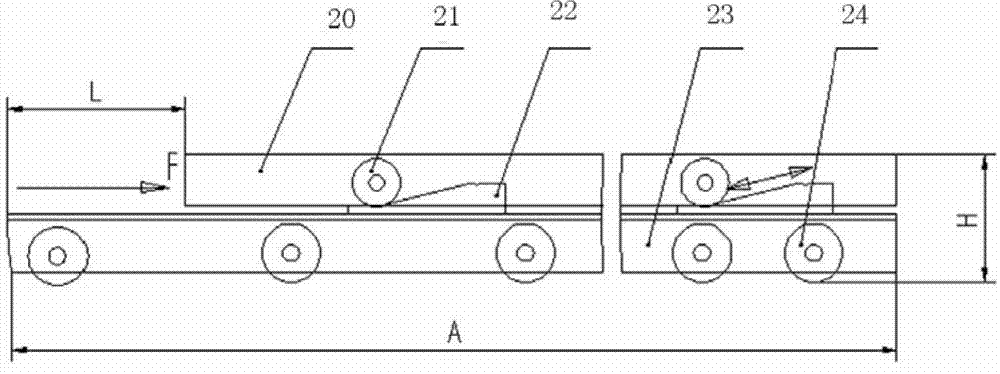
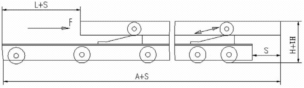
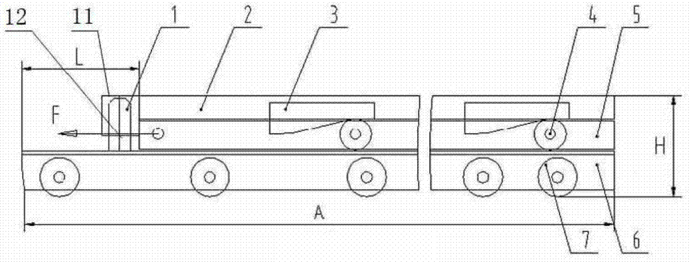
[0020] refer to image 3 and Figure 4 Shown: is the structural schematic view of the shuttle trolley type vertical lifting device of the present invention before and after lifting. The shuttle trolley type vertical lifting device includes a vertical guide mechanism 1, an upper trolley 2, an oblique block 3, a shuttle trolley wheel set 4, a shuttle trolley 5, a lower trolley 6 and a lower trolley wheel set 7.

[0021] Wherein, the vertical guide mechanism 1 is fixed on one side of the vertical lifting device, and includes a guide sleeve 11 and a ...


PUM


Abstract

The invention relates to a shuttling trolley type perpendicular lifting device. The shuttling trolley type perpendicular lifting device comprises a perpendicular guiding mechanism, an upper-layer trolley, wedges, a shuttling trolley wheel set, a shuttling trolley, a lower-layer trolley and a lower-layer trolley wheel set, wherein the perpendicular guiding mechanism is fixed to one side of a perpendicular lifting device body, the upper-layer trolley is arranged on the topmost portion of the perpendicular lifting device body, the wedges are fixedly arranged on the upper-layer trolley, the shuttling trolley is arranged in the middle of the perpendicular lifting device body, the shuttling trolley wheel set is arranged on the shuttling trolley in a sleeved mode, makes contact with rolling paths of the wedges, and can roll on the rolling paths, the lower-layer trolley is arranged in the lower portion of the perpendicular lifting device body, the lower-layer trolley wheel set is arranged on the lower-layer trolley in a sleeved mode, the shuttling trolley wheel set and rolling paths of the lower-layer trolley are combined to form a rolling pair in an assembled and connected mode, and the shutting trolley can roll on the lower-layer trolley. By the adoption of the shuttling trolley type perpendicular lifting device, the space occupied by devices matched with material trolleys can be reduced, the space occupied by workshops matched with the material trolleys can be reduced, and thus the cost is reduced.

Description

technical field [0001] The invention relates to a transport tool, in particular to a shuttle trolley type vertical lifting device for transporting materials in and out of heat treatment industrial furnaces in the non-ferrous industry. Background technique [0002] Furnace front transportation equipment is a special transportation vehicle for handling various materials in front of various industrial furnaces, referred to as feeder. It can realize various functions such as transfer, furnace charging and furnace discharge of materials to be processed. The vertical lifting device of the feeding trolley is mainly used to realize the vertical lifting and landing process of the feeding trolley, and it is the most critical component of each component of the feeding trolley. [0003] see figure 1 and figure 2 Shown in: is the structural representation before and after the lifting of the existing vertical lifting device. The existing vertical lifting device is a two-layer car str...

Claims


Application Information

Patent Timeline
Patent Type & Authority Applications(China)
IPC IPC(8): B66F9/065B66F9/08
Inventor 端木凡峰王爱国陈胜利
Owner LUOYANG LIHE MACHINERY
Why Eureka
Try Eureka