Hydraulic oil cylinder buffering piston for elevator

A hydraulic cylinder and buffer plug technology, which is applied in the field of hydraulic cylinder buffer plugs for elevators, can solve the problems of deep pit depth and high height in the elevator shaft, and achieve the effect of reducing the depth of the pit and reducing the overall height

Inactive Publication Date: 2017-02-15
罗元亮
View PDF0 Cites 2 Cited by
  • Summary
  • Abstract
  • Description
  • Claims
  • Application Information

AI Technical Summary

Problems solved by technology

[0003] Aiming at the deficiencies in the prior art, the present invention provides a hydraulic cylinder buffer plug for elevators to solve the problem in the prior art that the height of the hydraulic cylinder buffer plugs for elevators is too high and the pit depth of the elevator shaft is set too deep

Method used


Image

  • Hydraulic oil cylinder buffering piston for elevator
  • Hydraulic oil cylinder buffering piston for elevator
  • Hydraulic oil cylinder buffering piston for elevator

Examples


Embodiment 1

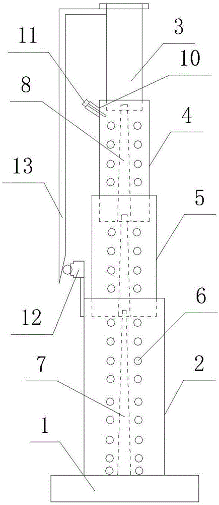
[0019] Such as Figure 1 to Figure 3 As shown, a hydraulic cylinder buffer plug for an elevator includes a base 1 , a hydraulic cylinder 2 disposed on the base 1 and a multi-stage plunger nested in the hydraulic cylinder 2 . The multi-stage plunger is composed of three plungers nested from top to bottom, and from top to bottom are the first-stage plunger 3 , the second-stage plunger 4 and the third-stage plunger 5 . Compression return springs 6 are provided between the plungers of all levels, between the three-stage plunger 5 and the hydraulic cylinder 2, and are used to restore each plunger after compression to the elongated state before compression. The spring 6 is installed inside the plunger and the inside of the hydraulic cylinder 2 . The bottom of the hydraulic oil cylinder 2 is provided with an oil passing rod 7, and the oil passing rod 7 can be hollow or solid. The bottoms of the first-stage plunger 3 , the second-stage plunger 4 and the third-stage plunger 5 are all...

Embodiment 2

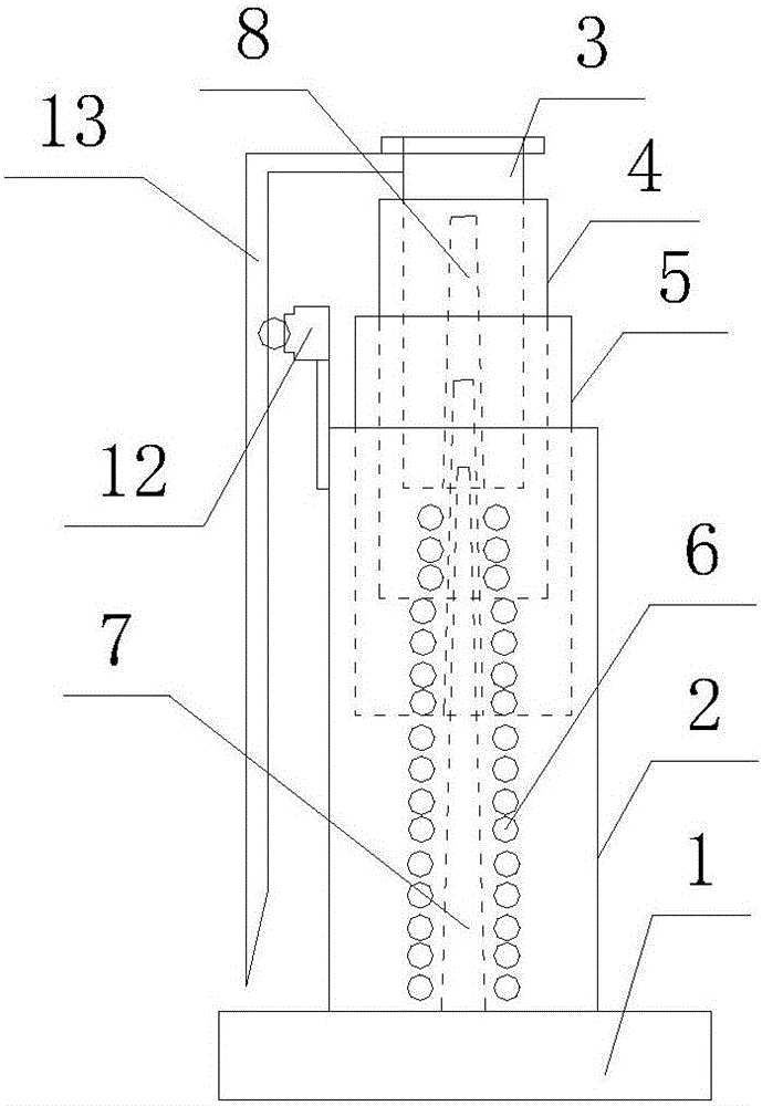
[0023] Such as Figure 4 and Figure 5As shown, a hydraulic cylinder buffer plug for an elevator includes a base 1 , a hydraulic cylinder 2 disposed on the base 1 and a multi-stage plunger nested in the hydraulic cylinder 2 . The multi-stage plunger is composed of three plungers nested from top to bottom, and from top to bottom are the first-stage plunger 3 , the second-stage plunger 4 and the third-stage plunger 5 . Compression return springs 6 are provided between the plungers of all levels, between the three-stage plunger 5 and the hydraulic cylinder 2, and are used to restore each plunger after compression to the elongated state before compression. The spring 6 is installed on the outside of the plunger, and the specific installation method is: one end of the compression return spring 6 is fixed on the outer side of the top circumference of the first-stage plunger 3, the other end is fixed on the outer side of the top circumference of the second-level plunger 4, and other...


PUM


Abstract

The invention discloses a hydraulic oil cylinder buffering piston for an elevator. The hydraulic oil cylinder buffering piston for the elevator comprises a base, and a hydraulic oil cylinder arranged on the base. The hydraulic oil cylinder buffering piston further comprises a multi-stage plunger piston which is embedded in the hydraulic oil cylinder in a sleeving manner, wherein the multi-stage plunger piston is formed by embedding and sleeving at least two plunger pistons from top to bottom; a compressing returning spring is arranged between the plunger pistons at every two stages, and the compressing returning spring is also arranged between the plunger piston at the lowest stage and the hydraulic oil cylinder; with the adoption of the compressing returning springs, each compressed plunger piston can be returned to an uncompressed extending state; an oil returning rod is arranged at the inner bottom part of the hydraulic oil cylinder; oil running holes through which the oil running rod passes are formed in the bottom part of the plunger pistons at all stages. According to the hydraulic oil cylinder buffering piston for the elevator, the multi-stage embedding and sleeving type plunger piston structure and the oil running rod structure are adopted to ensure that the overall compressing stroke of a buffer can be decomposed into the compressing stroke of the plunger piston at each stage on the premise that the compressing stroke can be met as the same requirement, thus the overall height of the oil cylinder and the compressed buffer can be effectively reduced, and as a result, the requirement of an elevator hoistway on the depth of a bottom pit can be reduced.

Description

technical field [0001] The invention relates to the field of buffers, in particular to an elevator hydraulic cylinder buffer plug for elevators. Background technique [0002] In the prior art, the hydraulic cylinder buffer plugs for elevators produced at home and abroad all use an oil cylinder, a plunger, and a conical oil passing rod as the main components, and use the damping force of the liquid flow to slow down the car when it falls. Shock, and use the spring to make it return. The basic principle is: when the car or the counterweight hits the buffer, the plunger moves downward, compressing the oil in the cylinder, so that the oil overflows into the plunger through the oil hole at the bottom of the plunger, and stops the car. During the process of moving the car or counterweight, its kinetic energy is converted into heat energy of the oil, which decelerates and stops the elevator. Because the traditional elevator hydraulic cylinder buffer plug adopts a single-stage str...

Claims


Application Information

Patent Timeline
Patent Type & Authority Applications(China)
IPC IPC(8): B66B5/28
CPCB66B5/282
Inventor 罗元亮
Owner 罗元亮
Why Eureka
Try Eureka