
Flow guiding platform conical valve for retarder

A cone valve and platform technology, applied in the direction of balance valve, lifting valve, valve details, etc., can solve the problems of large impact force, off-line, and dangerous shunting operation, and achieve small pressure overshoot, convenient processing, and light weight Effect

Active Publication Date: 2014-06-04
哈尔滨铁路减速顶调速研究有限公司
View PDF7 Cites 0 Cited by
  • Summary
  • Abstract
  • Description
  • Claims
  • Application Information

AI Technical Summary

Problems solved by technology

[0003] The purpose of the present invention is to solve the problem that the hydraulic flow of the high-load deceleration top has an excessive impact force on the existing cone valve, which easily leads to off-line accidents and brings danger to the shunting operation.

Method used


Image

  • Flow guiding platform conical valve for retarder
  • Flow guiding platform conical valve for retarder

Examples


specific Embodiment approach 1

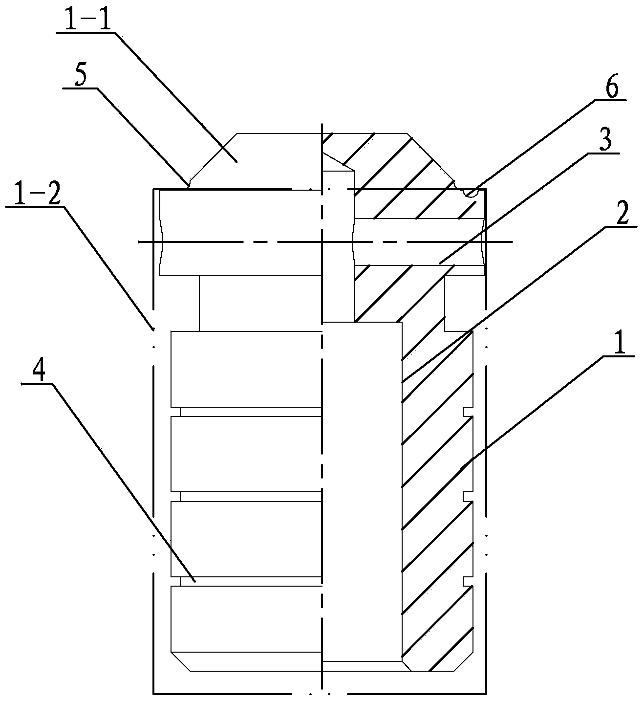
[0013] Specific implementation mode one: combine figure 1 Describe this embodiment, a conical valve of a diversion platform for a deceleration roof in this embodiment includes a valve body 1, and the valve body 1 includes a cone 1-1 and a diversion platform 1-2, and the diversion platform 1-2 It is a columnar platform, the cone 1-1 and the diversion platform 1-2 are fixedly arranged from top to bottom, the diversion platform 1-2 is provided with a stepped inner cavity 2, and the through hole 3 is pierced through the diversion platform 1 -2, and the through hole 3 is perpendicular to the diversion platform 1-2, and the bottom of the diversion platform 1-2 is provided with a plurality of grooves 4 from top to bottom along its outer wall, and the cone 1-1 The cone 1-1 at the intersection with the diversion platform 1-2 is provided with a cone pressure relief arc groove 5, and the diversion platform at the intersection of the cone 1-1 and the diversion platform 1-2 1-2 is provide...

specific Embodiment approach 2

[0014] Specific implementation mode two: combination figure 1 Describe this embodiment, the quantity of a plurality of grooves 4 of this embodiment is 4, and the width of described 4 grooves 4 is not equal, and the width of the first groove 4 counting from top to bottom is 3mm, and the remaining 3 Each groove 4 width is 0.5mm. Such a setting facilitates satisfying the diversion function. Other compositions and connections are the same as in the first embodiment.

specific Embodiment approach 3

[0015] Specific implementation mode three: combination figure 1 To describe this embodiment, the arc radii of the cone pressure relief arc groove 5 and the platform pressure relief arc groove 6 in this embodiment are both 0.4 mm. Such setting can effectively reduce the impact of the hydraulic flow on the cone valve. Other compositions and connections are the same as those in the second embodiment.

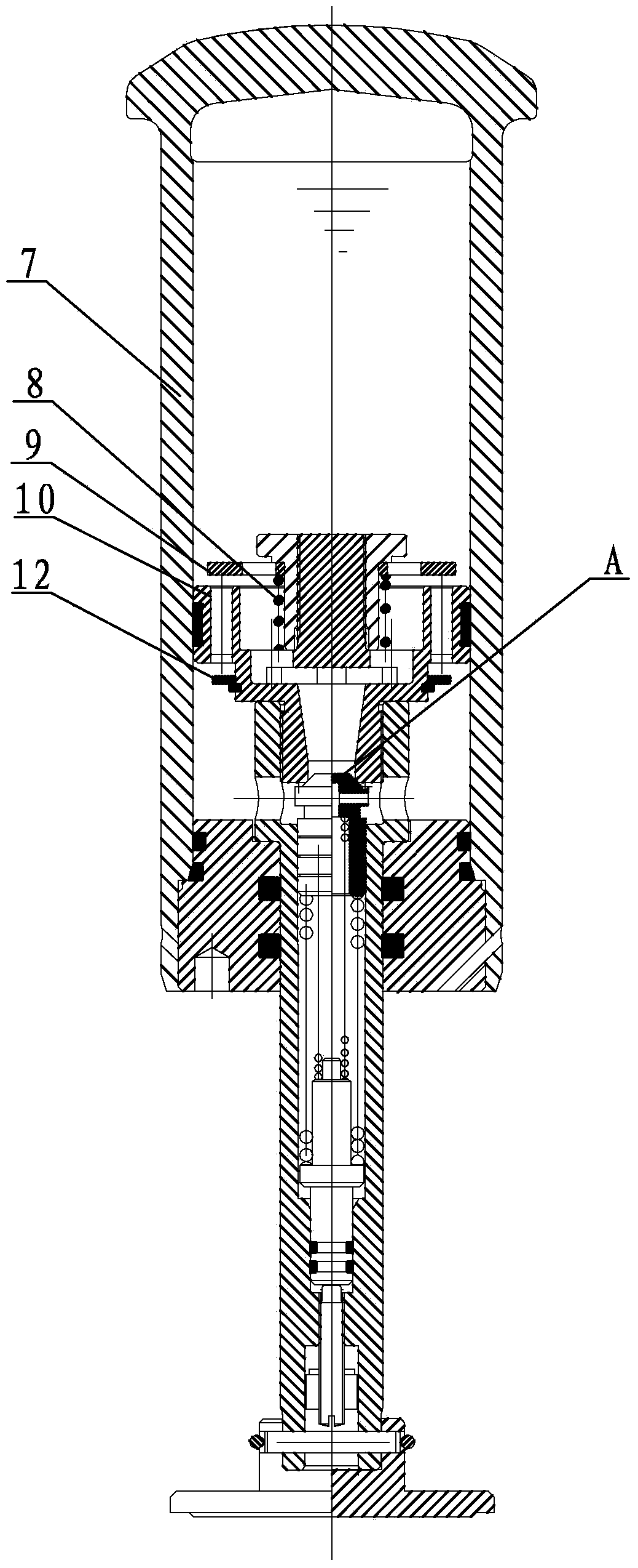
[0016] combine figure 2 Explain that the working principle of applying the diversion platform cone valve of the present invention to the high-load deceleration roof is as follows: (assuming that the diversion platform cone valve of the present invention is in the figure 2 Indicated as A)

[0017] When the speed is lower than the critical speed: When the rolling speed of the vehicle is lower than the critical speed set by the high-load deceleration top, the speed at which the sliding cylinder 7 is pressed down by the wheel is relatively low, and the flow generated by the oil in...


PUM


Abstract

The invention provides a flow guiding platform conical valve for a retarder, and relates to a flow guiding platform conical valve. The problems that the impact force of instant hydraulic flow of a high-load retarder on the existing conical valve is over large, so that off-line accidents are easily caused, and shunting service is dangerous are solved. A valve body of the flow guiding platform conical valve comprises a cone and a flow guiding platform, wherein the flow guiding platform is a columnar platform; the cone and the flow guiding platform are sequentially arranged fixedly from top to bottom; a step inner cavity is formed in the flow guiding platform; a through hole is formed in the upper portion of the flow guiding platform and is perpendicular to the flow guiding platform; a plurality of grooves are sequentially formed in the lower portion of the flow guiding platform from top to bottom along the outer side wall of the flow guiding platform; a cone pressure-relief arc-shaped groove is formed in the cone and in an intersection of the cone and the flow guiding platform; a platform pressure-relief arc-shaped groove is formed in the flow guiding platform and in an intersection of the cone and the flow guiding platform; and the cone pressure-relief arc-shaped groove is adjacent to the platform pressure-relief arc-shaped groove. The flow guiding platform conical valve is used for the retarder.

Description

technical field [0001] The invention relates to a diversion platform cone valve, in particular to a diversion platform cone valve for a high-load deceleration roof. Background technique [0002] With the development requirements of high-speed and heavy-duty railways at home and abroad, the speed-regulating equipment of high-load series deceleration jacks has been widely promoted and applied. The pressure valve is one of the core components of the high-load retarder, which directly determines whether the work of the high-load retarder is stable. However, due to the large hydraulic flow rate of the high-load deceleration top, the ordinary pressure valve is seriously affected by the hydraulic power, especially at high speeds, it is easy to generate excessive vertical reaction force that endangers driving safety. When the wheel passes through the head of the sliding cylinder, it is easy to cause Accidents such as off-lines occur, which brings danger to shunting operations. The...

Claims


Application Information

Patent Timeline
Patent Type & Authority Applications(China)
IPC IPC(8): F16K1/38F16K1/52F15B13/02B61K7/02
CPCB61K7/02F16K1/38F16K1/52F16K17/04F16K27/02F16K47/023
Inventor 赵连祥曾祥荣王潜胡东东曹永鹏陈峰郭爽安慧
Owner 哈尔滨铁路减速顶调速研究有限公司
Learn More