Ice storage tank

An ice storage tank and ice layer technology, which is applied in household heating, lighting and heating equipment, space heating and ventilation, etc., can solve the problems of placement restrictions, blockage of air-conditioning water channels, occupying building space, etc., and achieve reliable performance , reduce investment and save construction space

Inactive Publication Date: 2014-06-04
SHANGHAI AIRUTE AIR CONDITIONING SYST
View PDF1 Cites 0 Cited by
  • Summary
  • Abstract
  • Description
  • Claims
  • Application Information

AI Technical Summary

Problems solved by technology

This ice storage tank also has some defects, such as the phenomenon that the air-conditioning water channel may be blocked when melting ice; moreover, such a shell-and-tube ice storage tank cannot meet the requirements of a large-capacity ice storage air-conditioning system. If it is modularized, due to The shape is a cylinder, and its placement form is easily restricted by the site space, which will occupy valuable building space and other issues

Method used


Image

  • Ice storage tank
  • Ice storage tank
  • Ice storage tank

Examples


Embodiment 1

[0042] It should be noted that the diagrams provided in this embodiment are only schematically illustrating the basic idea of ​​the present invention, and only the components related to the present invention are shown in the diagrams rather than the number, shape and shape of the components in actual implementation. Dimensional drawing, the type, quantity and proportion of each component can be changed arbitrarily during actual implementation, and the component layout type may also be more complicated.

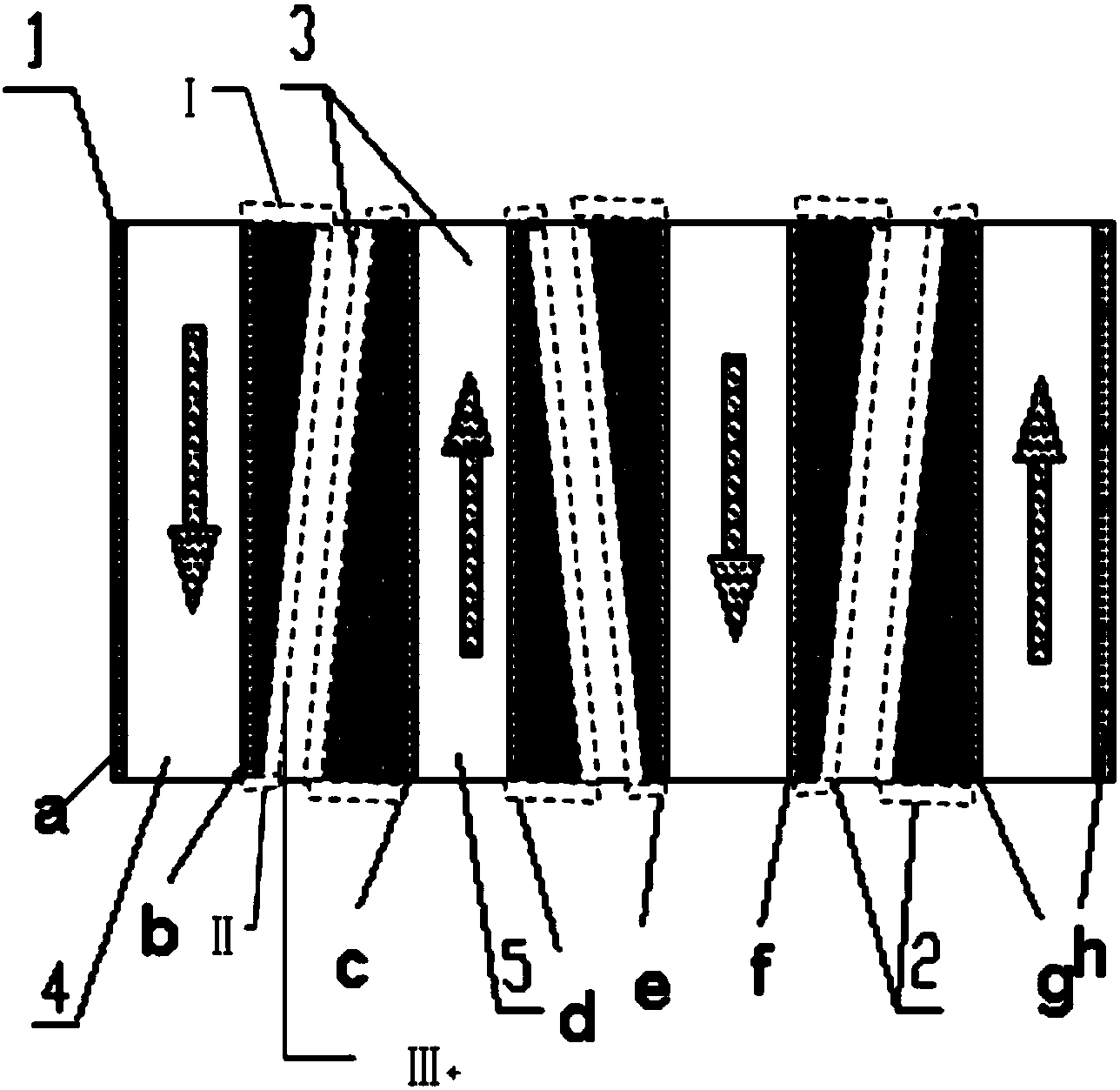
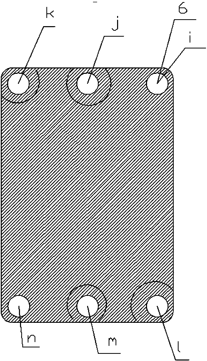
[0043] Figure 1 to Figure 6 It is a relevant diagram of the vertical external ice-melting ice storage tank according to an embodiment of the present invention. The ice storage tank includes: a group of heat exchange plates a, b, c, d, e, f, g, h with through holes, low-temperature fluid inlet ports 11, 14, low-temperature fluid outlet ports 13, 16, air-conditioning water Inlet interface 12, air-conditioning water outlet interface 15. Interleaved air-conditioning water chann...

Embodiment 2

[0062] It should be noted that the diagrams provided in this embodiment are only schematically illustrating the basic idea of ​​the present invention, and only the components related to the present invention are shown in the diagrams rather than the number, shape and shape of the components in actual implementation. Dimensional drawing, the type, quantity and proportion of each component can be changed arbitrarily during actual implementation, and the component layout type may also be more complicated.

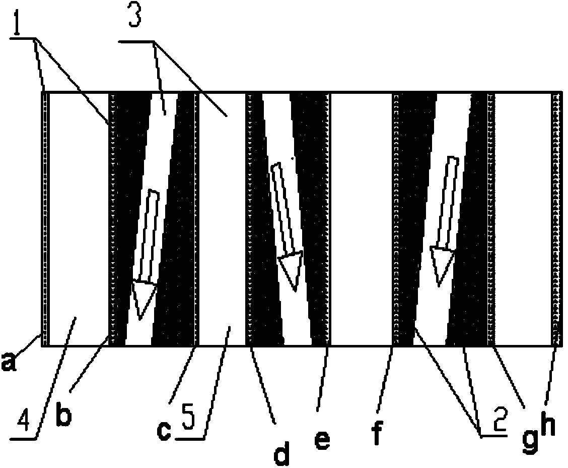
[0063] Figure 7-12 It is a relevant schematic diagram of the horizontal external ice-melting ice-storage tank of Embodiment 2 of the present invention. The ice storage tank includes: a group of heat exchange plates a, b, c, d, e, f, g, h with through holes, low-temperature fluid inlet ports 21, 26, low-temperature fluid outlet ports 23, 24, air-conditioning water Inlet interface 22, air-conditioning water outlet interface 25. Interleaved air-conditioning water channels and ...


PUM


Abstract

The invention provides an ice storage tank which mainly comprises a set of heat exchange plates with through holes, a cryogenic fluid inlet connector, a cryogenic fluid outlet connector, an air conditioner water inlet connector and an air conditioner water outlet connector. Air conditioner water channels and cryogenic fluid channels which are staggered with each other are formed between the heat exchange plates. The flowing directions of cryogenic fluid of the adjacent cryogenic fluid channels are opposite so as to form staggered flow. The ice storage tank is characterized in that an ice blocking support for ice blocks is fixedly formed between the heat exchange plates with the air conditioner water channels in each set. According to the ice storage tank, due to the fact that the ice blocking support with through holes for the wedge-shaped ice blocks is fixedly formed between the heat exchange plates with the air conditioner water channels in each set, when ice is molten, the ice blocks which are not completely molten are blocked by the ice blocking supports, and therefore the molten speed of the ice blocks is improved.

Description

technical field [0001] The invention relates to the technical field of ice storage air conditioning, in particular to an ice storage tank in an ice storage air conditioning system. Background technique [0002] Due to the rapid growth of my country's economy, electricity consumption has also increased rapidly, especially during peak hours, and the contradiction of insufficient power supply in peaks and excess in troughs has become more and more prominent. Therefore, the power supply department adopts a time-of-use electricity price policy to shift peaks and fill valleys. The power consumption of air conditioners accounts for about 30% of the total power consumption of the power grid, which is an important reason for the peak-valley load difference in the power grid. The ice-storage air-conditioning system uses the low-cost off-peak electricity to store ice at night to store cold energy, and uses less or no main engine cooling during the peak electricity consumption period w...

Claims


Application Information

Patent Timeline
Patent Type & Authority Applications(China)
IPC IPC(8): F24F5/00
Inventor 张小力
Owner SHANGHAI AIRUTE AIR CONDITIONING SYST
Why Eureka
Try Eureka