
One-time molding tray tooling with LED light strips of any cross-sectional shape surrounding the glue

A technology of LED strips and cross-sections, applied to electrical components, circuits, semiconductor devices, etc., can solve problems such as complex production process, product defects and hidden quality problems, difficulty in large-scale and high-efficiency production, and achieve optimized manufacturing process, High-efficiency batch production and the effect of reducing production costs

Active Publication Date: 2016-03-30
江苏智慧光彩光电科技有限公司
View PDF6 Cites 0 Cited by
  • Summary
  • Abstract
  • Description
  • Claims
  • Application Information

AI Technical Summary

Problems solved by technology

[0002] LED filaments in the prior art, also known as LED lamp sticks or LED lamp posts, need to be coated with silica gel on both sides of the front and back during production and processing. The production process is relatively complicated, and it is difficult to achieve large-scale and high-efficiency In addition, the side of the LED filament obtained in this process is not covered with silica gel, resulting in certain defects and quality risks in the product

Method used


Image

  • One-time molding tray tooling with LED light strips of any cross-sectional shape surrounding the glue
  • One-time molding tray tooling with LED light strips of any cross-sectional shape surrounding the glue
  • One-time molding tray tooling with LED light strips of any cross-sectional shape surrounding the glue

Examples


Embodiment Construction

[0022] The preferred embodiments of the present invention are described in detail below, so that the advantages and features of the present invention can be more easily understood by those skilled in the art, so as to define the protection scope of the present invention more clearly.

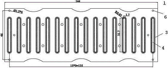
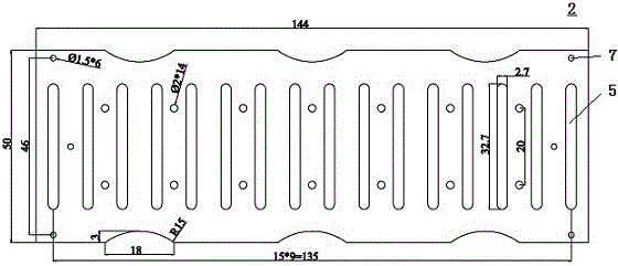
[0023] See attached figure 1 to attach Figure 5 As shown, the LED light bar with any cross-sectional shape described in this embodiment surrounds the glue-filled one-time forming tray tooling, which includes a molded bar tray 1 and a tray cover plate 2, and the overall size of the two matches. The upper surface of the molding tray 1 is provided with a plurality of positioning areas 3 for placing LED light strips. The positioning area 3 has a concave plastic molding surface 4 for silicone colloid molding. The expansion coefficient of the plastic molding surface 4 and the silicone colloid is the same. Therefore, in the subsequent drying process, since the silicone colloid and the plastic molding...


PUM


Abstract

The invention discloses a tray tool formed through surrounding glue filling in a one-off mode and provided with LED light bars of arbitrary cross-sectional shapes. The tray tool comprises a die bar tray and a tray cover plate. The upper surface of the die bar tray is provided with multiple locating areas used for containing the LED light bars. Each locating area is provided with a sunken plastic forming surface used for colloidal silica forming. The tray cover plate is installed on the top of the die bar tray to locate the LED light bars. The tray cover plate is provided with multiple corresponding hollowed-out areas so that the LED light bars can be exposed from the upper portion of the tray cover plate. The tray tool has the advantages that the manufacturing process is optimized, high-efficiency batch production is realized, and production cost is lowered.

Description

technical field [0001] The invention relates to the technical field of LEDs. Background technique [0002] LED filaments in the prior art, also known as LED lamp sticks or LED lamp posts, need to be coated with silica gel on both sides of the front and back during production and processing. The production process is relatively complicated, and it is difficult to achieve large-scale and high-efficiency In addition, the side of the LED filament obtained in this process is not covered with silica gel, resulting in certain defects and quality risks in the product. Contents of the invention [0003] In order to overcome the deficiencies in the prior art, the object of the present invention is to provide a tooling capable of one-time injection molding of LED filaments. [0004] In order to achieve the above purpose, the present invention provides a tooling for forming trays with LED light strips of any cross-sectional shape around the glue filling, including a mold tray and a t...

Claims


Application Information

Patent Timeline
Patent Type & Authority Patents(China)
IPC IPC(8): H01L33/52
CPCH01L33/54H01L33/56H01L2933/005
Inventor 周有旺周造轩周红玉
Owner 江苏智慧光彩光电科技有限公司
Learn More