Strong combined transparent multi-angle light-emitting LED light bar and preparation method thereof

A LED light bar and multi-angle technology, applied in lighting and heating equipment, semiconductor devices of light-emitting elements, light sources, etc., can solve problems such as difficult large-scale high-efficiency production, complicated production process, inconvenient use and installation process, etc., to achieve High-efficiency mass production, optimized manufacturing process, and reduced defective rate

Active Publication Date: 2016-08-24
江苏智慧光彩光电科技有限公司
View PDF4 Cites 0 Cited by
  • Summary
  • Abstract
  • Description
  • Claims
  • Application Information

AI Technical Summary

Problems solved by technology

[0002] The LED filament in the prior art, also known as LED lamp stick or LED lamp post, uses a transparent substrate with a chip on it, and positive and negative electrode terminals are respectively installed at both ends of the substrate. The installation process of electrode terminals at both ends is relatively complicated, and it is difficult to produce large-scale and high-efficiency production. In addition, there are electrode terminals at both ends, which makes it inconvenient to use and install.

Method used


Image

  • Strong combined transparent multi-angle light-emitting LED light bar and preparation method thereof
  • Strong combined transparent multi-angle light-emitting LED light bar and preparation method thereof
  • Strong combined transparent multi-angle light-emitting LED light bar and preparation method thereof

Examples


Embodiment Construction

[0021] The preferred embodiments of the present invention are described in detail below, so that the advantages and features of the present invention can be more easily understood by those skilled in the art, so as to define the protection scope of the present invention more clearly.

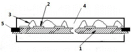
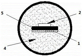
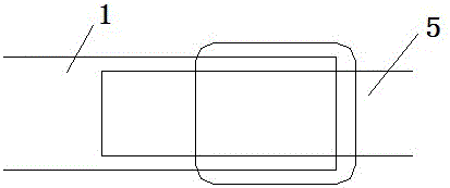
[0022] See attached figure 1 with attached figure 2 shown, with figure 1 It is a schematic diagram of the side section structure of the strongly combined transparent multi-angle light-emitting LED light bar according to the present invention, and the attached figure 2 It is a cross-sectional structural schematic diagram of a strongly combined transparent multi-angle light-emitting LED light bar according to the present invention. The strongly combined transparent multi-angle light-emitting LED light bar in the figure includes a transparent substrate 1, a plurality of LED chips 2 arranged on the transparent substrate 1, electrode terminals 5 arranged at both ends of the transparent substrate ...


PUM


Abstract

The present invention disclosed a powerful combined transparent multi -angle light -emitting LED light bar, including transparent substrates, multiple LED chips set on a transparent substrate, electrical terminals set at both ends of transparent substrates, and multiple LED chips on transparent substrates pass through through transparent substrates.The golden wire is connected to the electrode, and the transparent substrate, the LED chip, and the outer part of the gold wire ejected the surround package with a silicone gel to form a column. The electrodes and transparent substrates at both ends are tightened by injection plastic parcel or stamping.It also provides a preparation method for a strong combination of transparent transparent multi -angle as above. First of all, the transparent substrate uses vacuum chrome -covered silver, and then uses LED chips and gold threads on the transparent substrate.Methods are covered with silicone gels outside the transparent substrate, LED chip, and golden threads. Finally, the electrical terminal and transparent substrate are tightened by injection plastic parcel or stamping.The beneficial effect of the present invention is to optimize the manufacturing process and achieve high -efficiency mass production; reduce production costs and reduce adverse rates.

Description

technical field [0001] The invention relates to the technical field of LEDs. Background technique [0002] The LED filament in the prior art, also known as LED lamp stick or LED lamp post, uses a transparent substrate with a chip on it, and positive and negative electrode terminals are respectively installed at both ends of the substrate. The installation process of the electrode terminals at both ends is relatively complicated, and it is difficult to produce large-scale and high-efficiency production. In addition, the electrode terminals at both ends cause inconvenience in the use and installation process. Contents of the invention [0003] In order to overcome the deficiencies in the prior art, the object of the present invention is to provide a method for preparing a strong combined transparent multi-angle light-emitting LED light strip with high efficiency and mass production. [0004] In order to achieve the above objectives, the present invention provides a strongly...

Claims


Application Information

Patent Timeline
Patent Type & Authority Patents(China)
IPC IPC(8): H01L33/48H01L33/56F21S2/00F21Y115/10F21K9/20
CPCH01L25/0753H01L33/48H01L33/56H01L33/62F21S2/00F21V23/06H01L2933/005H01L2933/0033F21Y2101/00H01L2924/181H01L2224/48091H01L2224/48137H01L2924/00014H01L2924/00012
Inventor 周有旺周红玉
Owner 江苏智慧光彩光电科技有限公司
Why Eureka
Try Eureka