
Upper parts for fittings

A technology of parts and accessories, which is applied in the field of valve parts, can solve the problems of lip seal deformation and damage the sealing effect of lip seal, and achieve the effect of avoiding deformation

Active Publication Date: 2018-04-06
FLUHS DREHTECHN
View PDF2 Cites 0 Cited by
  • Summary
  • Abstract
  • Description
  • Claims
  • Application Information

AI Technical Summary

Problems solved by technology

Here, the known valve top has the disadvantage that, depending on the fluid pressure that occurs, deformations of the lip seal can occur, whereby the sealing effect of the lip seal can be impaired

Method used


Image

  • Upper parts for fittings
  • Upper parts for fittings
  • Upper parts for fittings

Examples


Embodiment Construction

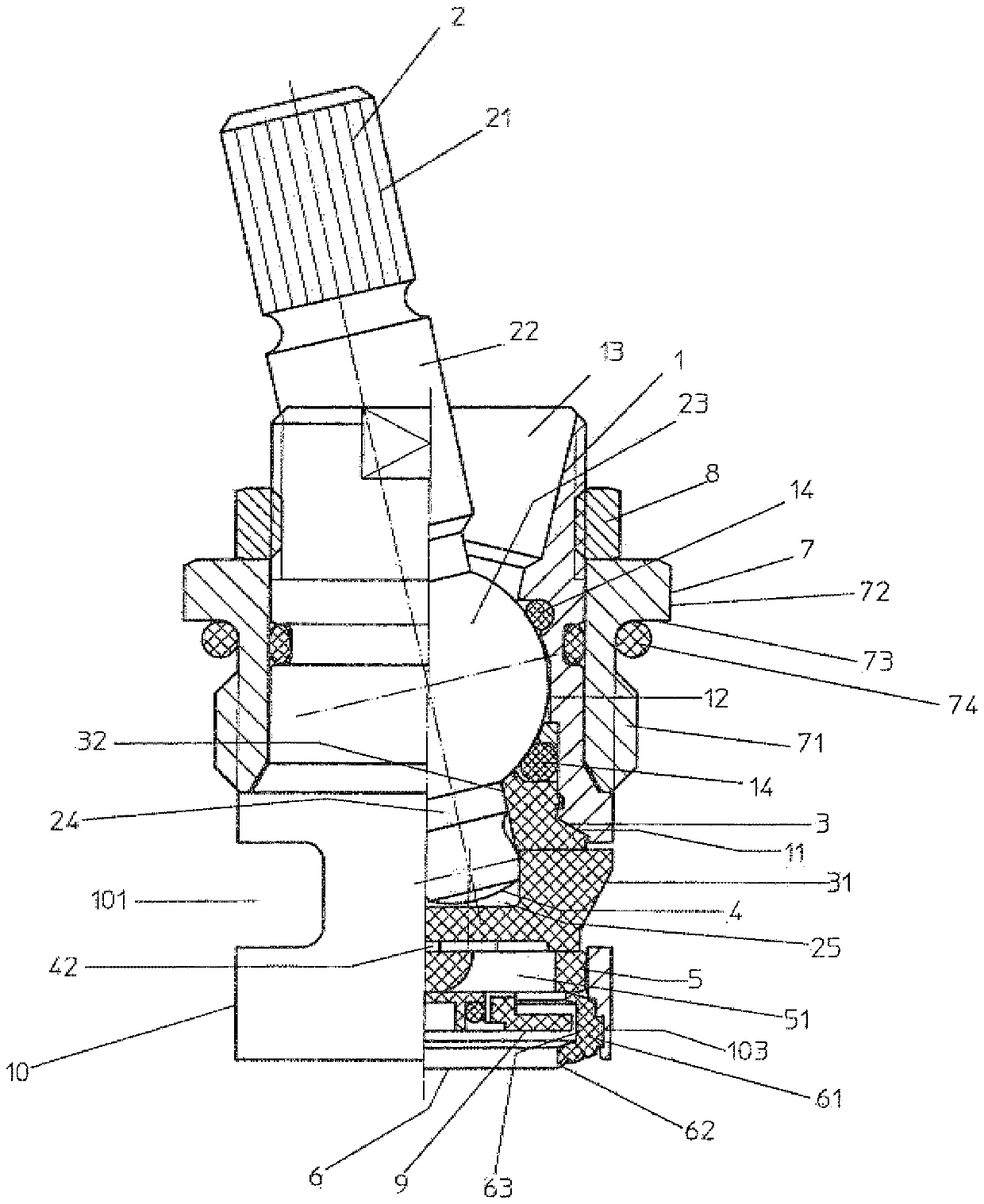
[0022] The valve top part chosen as the exemplary embodiment has a top part 1 through which a spindle 2 guided radially passes through. The spindle 2 is guided through a rotationally fixed disk guide 3 and is positively connected to a control disk 4 , which is in turn guided in the disk guide 3 . The control disk 4 is in contact with an inlet disk 5 which is held in the top part 1 and which is in contact on its side facing away from the control disk 4 with a seal 6 which accommodates a flow restrictor 9 . Arranged centrally around the top part 1 is a coupling sleeve 7 which is fastened on its side facing the seal 6 with a union nut 8 .

[0023] The top part 1 consists of a symmetrical hollow body which is open at both ends. The top part 1 has a sleeve-shaped part 10 on its side facing the fitting (not shown). The top part 1 has a central inlet at the free end of the sleeve-shaped part 10 . A passage window 101 is provided in the sleeve-shaped part 10 . In a development of ...


PUM


Abstract

The valve bonnet has head piece (1) through which center of a spindle (2) is passed, to actuate valve structure, so that valve structure rests against the valve seat of housing. A sealing device is arranged between valve structure and valve seat. The sealing device comprises a sealing ring which is in the form of a lip seal (6) held in position by a support element which is constructed as a flow limiter (9).

Description

technical field [0001] The invention relates to a valve upper part for an armature with a top part through which a spindle passes through, via which a valve body abutting against a valve seat of a housing can be actuated, wherein A sealing device is arranged between the valve body and the valve seat, which includes a sealing ring designed as a lip seal. Background technique [0002] The flow of fluid from the fitting is controlled by means of the upper part of the valve. For this purpose, the upper part of the valve is screwed into the housing of the fitting by means of the top part; the rotary handle or lever is inserted onto its spindle. In the known valve top (cf. DE 202 03 228 U1) two discs are provided for flow control. The disc is made of ceramic material. One of the two disks (the control disk) is arranged rotatably in the valve upper part by means of a drive connected to the spindle. The other disc part (entry disc, Einlassscheibe) is a fixed seat disc. As the c...

Claims


Application Information

Patent Timeline
Patent Type & Authority Patents(China)
IPC IPC(8): F16K3/08G05D7/01
CPCF16K3/0209G05D7/012
Inventor F.图劳
Owner FLUHS DREHTECHN
Learn More