Eureka AIR delivers breakthrough ideas for toughest innovation challenges, trusted by R&D personnel around the world.

U-shaped pipe pushing device, automatic pipe passing device and operation method of U-shaped pipe pushing device

A technology of pushing device and driving device, applied in assembly machines, metal processing equipment, manufacturing tools, etc., can solve the problems of unfavorable heat transfer product flow production, damage to pipe parts, high labor intensity, and achieve uniform distribution of insertion force, The effect of improving production efficiency and reducing labor intensity

Active Publication Date: 2014-06-11
GREE ELECTRIC APPLIANCES INC
View PDF5 Cites 5 Cited by
  • Summary
  • Abstract
  • Description
  • Claims
  • Application Information

AI Technical Summary

Problems solved by technology

Then take the long U-shaped tube. The U-shaped tube is generally a copper tube. Manually use one hand to correct the long U copper tube, align it with the hole on the pre-piercing tube device, and push the long U into the corresponding hole with the other hand. In the hole of the pre-threading device, this method has high labor intensity, low efficiency, and is easy to cause damage to the pipe-threading parts. It is difficult for unskilled employees to perform this job, and manual pipe threading is not conducive to heat transfer products. Realization of flow production

Method used


Image

  • U-shaped pipe pushing device, automatic pipe passing device and operation method of U-shaped pipe pushing device
  • U-shaped pipe pushing device, automatic pipe passing device and operation method of U-shaped pipe pushing device
  • U-shaped pipe pushing device, automatic pipe passing device and operation method of U-shaped pipe pushing device

Examples


Embodiment Construction

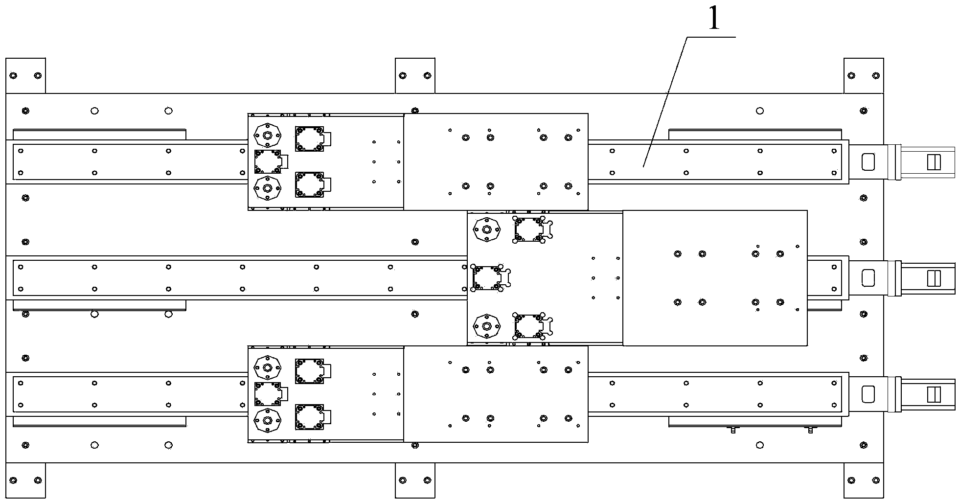
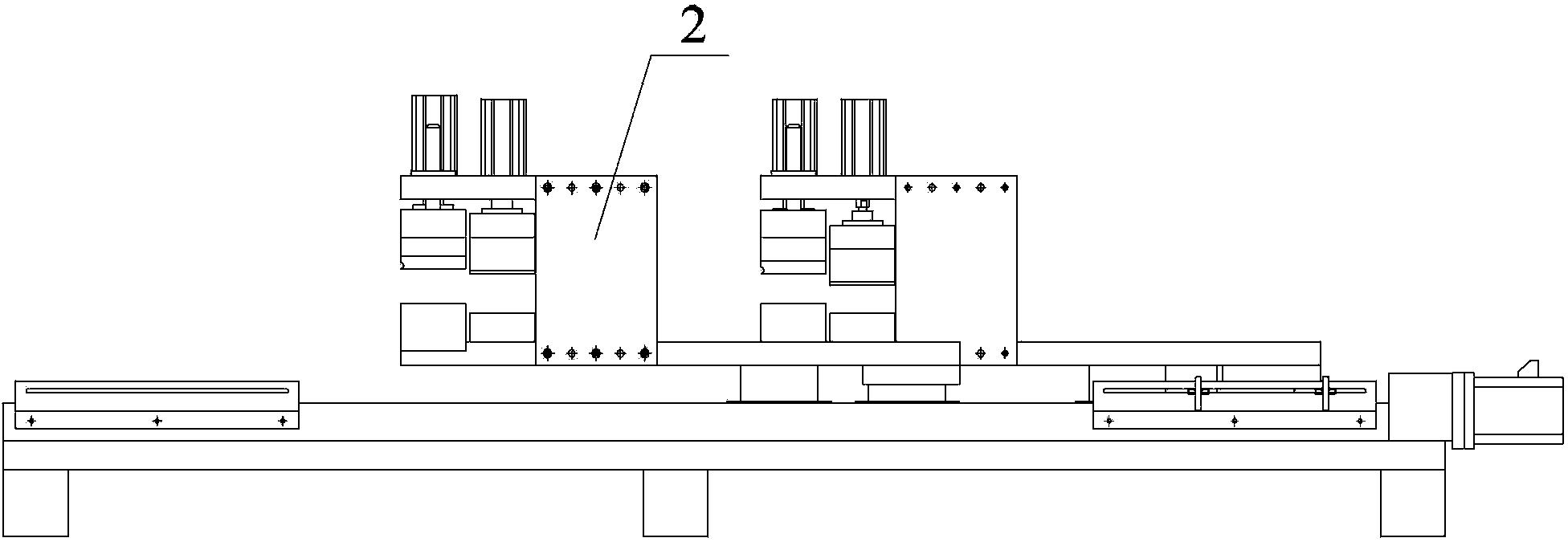
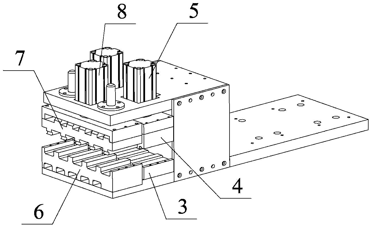
[0032] The invention discloses a U-tube pushing device, which reduces the labor intensity in the process of two devices threading the pipes; the invention also provides an automatic pipe threading machine.

[0033] The technical solutions in the embodiments of the present invention will be clearly and completely described below in conjunction with the accompanying drawings in the embodiments of the present invention. Obviously, the described embodiments are only some, not all, embodiments of the present invention. Based on the embodiments of the present invention, all other embodiments obtained by persons of ordinary skill in the art without making creative efforts fall within the protection scope of the present invention.

[0034] Such as Figure 1-Figure 5 as shown, figure 1 The top view of the U-tube pushing device provided by the present invention; figure 2 for figure 1 side view of image 3 for figure 1 Schematic diagram of the structure of the clamping device; Fi...


PUM


Abstract

The invention provides a U-shaped pipe pushing device, which comprises a plurality of linear modules in parallel arrangement, wherein each linear module respectively comprises a linear guide rail, in addition, the guide directions of the linear guide rails are identical, a clamping device used for clamping two parallel straight pipes of U-shaped pipes is respectively arranged on a slide seat of each linear guide rail, a plurality of clamping grooves for accommodating U-shaped parts of the U-shaped pipes are parallelly formed in the clamping devices, and the clamping directions of the clamping devices are vertical to the support direction of the slide seats. Through the clamping devices, pipelines of linear parts of a plurality of U-shaped pipes are mutually parallelly clamped between the clamping devices, during the transmission, the U-shaped pipes are pushed in the length direction of a linear pipeline, through the arrangement of a plurality of parallel linear modules, during the conveying, the U-shaped pipes are pushed in the length direction of the linear pipelines, through the arrangement of a plurality of side-by-side modules, the linear modules positioned in different positions are controlled to move in different work hours, the installation intensity in different positions of fins and the U-shaped pipes are continuously regulated in the installation process, and the pipe passing difficulty is reduced. The invention also provides an automatic pipe passing device. The invention also provides an operation method of the U-shaped pipe pushing device.

Description

technical field [0001] The invention relates to the technical field of automatic pipe threading machine production, and more specifically relates to a U-tube pushing device, an automatic pipe threading machine and an operation method for the U-tube pushing device. Background technique [0002] In the prior art, U-shaped tubes are used as a heat transfer device for gas-liquid transfer, and its structure includes a plurality of U-shaped tubes arranged in parallel in the length direction. A plurality of fixed support plates in the length direction are supported, and U-shaped tubes are interspersed and arranged on the fixed support plates. [0003] In the prior art, the manual operation method is often used to realize the pipe threading work of the U-shaped pipe on the fixed support component. The platform clamps the pre-piercing device. Then take the long U-shaped tube. The U-shaped tube is generally a copper tube. Manually use one hand to correct the long U copper tube, alig...

Claims


Application Information

Patent Timeline
IPC IPC(8): B23P21/00
CPCB23P21/002B23P2700/09
Inventor 孙秋元尹显椿赖丽娟邱雄胜白建文高景志
Owner GREE ELECTRIC APPLIANCES INC
Why Eureka
Eureka Blog
Learn More