Steel pipe rack

A technology for placing racks and steel pipes, applied in tool storage devices, manufacturing tools, etc., can solve the problems of inconvenient movement of steel pipes, uneven surfaces, and collision of steel pipes.

Inactive Publication Date: 2014-06-11
JIANGSU XINSHUN STAINLESS STEEL PROD
View PDF0 Cites 5 Cited by
  • Summary
  • Abstract
  • Description
  • Claims
  • Application Information

AI Technical Summary

Problems solved by technology

[0002] During the production and processing of steel pipes, it is sometimes necessary to smear paint on its outer wall. If it is placed directly on a plane support after painting, the round surface structure of the steel pipe will cause it to swing from side to side, causing collisions between the painted steel pipes, causing surface damage. It is not smooth or scratches the paint, etc., and the steel pipe that moves left and right will be inconvenient to move. Therefore, it is necessary to provide a shelf for the painted steel pipe

Method used


Image

  • Steel pipe rack
  • Steel pipe rack

Examples


Embodiment Construction

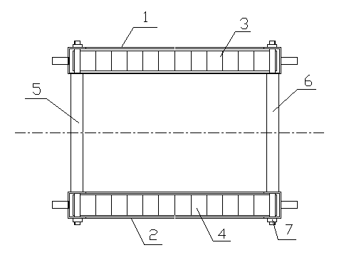
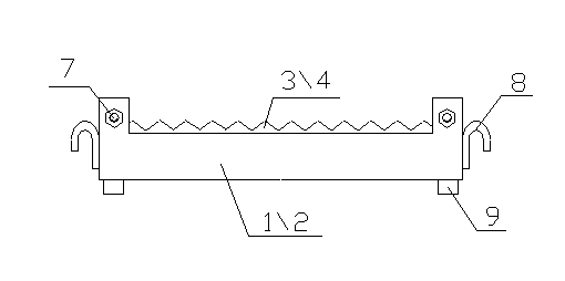
[0010] Such as figure 1 , 2 As shown, a steel pipe placement frame of the present invention includes two identical supports 1, 2, the supports 1, 2 are hollow structures with upward openings, and copper pipe seats 3, 2 are respectively placed in the supports 1, 2. 4. The upper surfaces of the copper tube holders 3 and 4 are serrated, and the upper and lower ends of the serrations are rounded, the brackets 1 and 2 are placed in parallel, and are passed through two connecting rods 5 and 6 Parallel and fixedly connected, the ends of the connecting rods 5 and 6 are provided with nuts 7 to fix the supports 1 and 2, and the end faces of the two ends of the supports 1 and 2 are respectively vertically welded with downwardly bent hooks 8, The four corners of the brackets 1 and 2 are respectively provided with cylinder feet 9 .

[0011] When the present invention works, the steel pipes are placed horizontally on the supports 1 and 2. Since the upper surfaces of the copper pipe seats ...


PUM


Abstract

The invention provides a steel pipe rack which comprises two identical supports. Each of the supports is of a hollow structure with an upward opening. Copper pipe seats are respectively arranged in the two supports. The upper surfaces of the two copper pipe seats are indented, the upper and lower ends of indented teeth are chamfered, and the two supports are parallelly arranged and fixedly connected through two connecting rods. Ends of the two supports are provided with nuts to fix the supports, end faces of two ends of the two supports are respectively perpendicularly welded with hooks bent downwardly, and cylindrical support legs are arranged at four corners of the two supports. The steel pipe rack has the advantages that the upper surfaces of the copper pipe seats are indented, steel pipes can be stably arranged between two indented teeth and cannot move. The hooks bent downwardly are welded on the supports, which facilitates lifting and transporting of the rack. The cylindrical support legs are arranged at the four corners of the supports, so that many racks can be stacked upwards, and space is reasonably utilized.

Description

technical field [0001] The invention relates to a steel pipe placing frame. Background technique [0002] During the production and processing of steel pipes, it is sometimes necessary to smear paint on its outer wall. If it is placed directly on a plane support after painting, the round surface structure of the steel pipe will cause it to swing from side to side, causing collisions between the painted steel pipes, causing surface damage. Unsmooth or scratch paint etc., and the steel pipe that moves left and right also can be inconvenient to move, therefore, it is necessary to provide a kind of placement frame of paint steel pipe. Contents of the invention [0003] In order to overcome the deficiencies of the prior art, the present invention develops a steel pipe placement frame, which includes two identical supports, both of which are hollow structures with upward openings, and copper bars are respectively placed in the two supports. Tube base, the upper surfaces of the ...

Claims


Application Information

Patent Timeline
Patent Type & Authority Applications(China)
IPC IPC(8): B25H3/04
Inventor 尤善斌
Owner JIANGSU XINSHUN STAINLESS STEEL PROD
Why Eureka
Try Eureka