
comb conveyor belt

A conveyor belt and comb stripping technology, applied in conveyors, threshing equipment, belt fasteners, etc., can solve problems such as inability to adapt to long-term operation, shortening of conveyor belt service life, fatigue and heating of lap joints, etc. The effect of removing efficiency, reducing breakage and increasing flexibility

Inactive Publication Date: 2016-04-20
培禾新地科技股份有限公司
View PDF6 Cites 0 Cited by
  • Summary
  • Abstract
  • Description
  • Claims
  • Application Information

AI Technical Summary

Problems solved by technology

The traditional conveyor belt can only be integrally formed with natural rubber. Due to the high elongation of the rubber, it is easy to cause the conveyor belt to elongate too much when used in the threshing mechanism, which cannot adapt to continuous long-term operation.
At present, the most widely used is the polyester (polyester) fabric skeleton and rubber mixed and vulcanized combing conveyor belt. The traditional manufacturing method is to cut the flat belt-shaped conveyor belt into a conveyor belt that meets the unfolded length, and the incision is straight. , and then connect the first and last cuts to form an endless conveyor belt. The fatal defect of the conveyor belt in this manufacturing method is that when it is in circular motion, the joint will be delaminated and broken due to fatigue and heat, resulting in a greatly reduced service life of the conveyor belt. , which limits the popularization and application of this kind of comb conveyor belt on the harvesting and threshing mechanism

Method used


Image

  • comb conveyor belt
  • comb conveyor belt
  • comb conveyor belt

Examples


Embodiment Construction

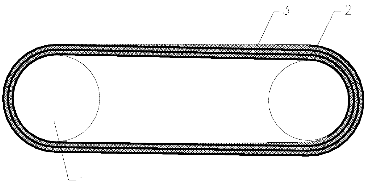
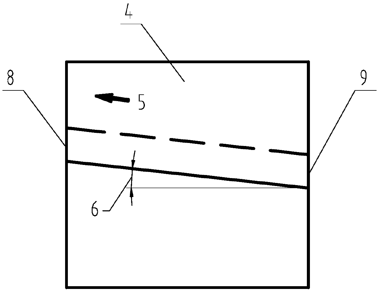
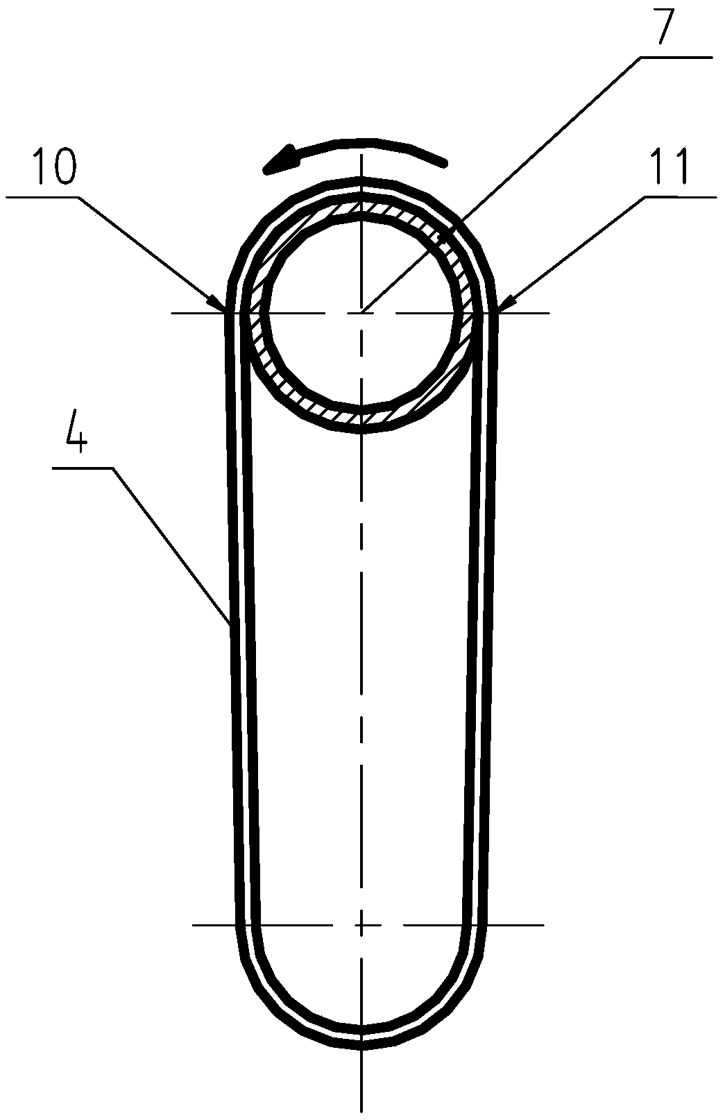
[0013] The preferred embodiment of the present invention is like this: with reference to Figure 1 ~ Figure 3 , the polyester fabric skeleton is wound more than one circle without interruption between two custom-made rollers 1 to make a multi-layer annular polyester fabric skeleton 2. During the winding process, natural rubber is evenly laid on the surface of the skeleton 3. Accelerators, vulcanizing agents, softeners, and fillers are added to the natural rubber 3 in a certain proportion, and finally the multi-layer annular polyester fabric skeleton 1 and the natural rubber 2 are integrally bonded by a vulcanization process to form a conveyor belt . The multi-layer annular polyester fabric skeleton 2 is used to increase the flexibility and strength of the conveyor belt, so that the conveyor belt can bear greater pulling force, which can improve the life of the conveyor belt several times. On the surface of the polyester (polyester) fabric skeleton 2 The natural rubber 3 laid ...


PUM


Abstract

The invention discloses a stripping conveying belt, which comprises a polyester fabric framework and natural rubber, and is characterized in that the polyester fabric framework in a conveying belt interlayer is a multilayer annular polyester fabric framework which is formed by continuously winding a framework material between two customized wheel rolls for more than one circle; the start end and the tail end which are wound on the framework are lapped and overlaid; a slant lap joint mode is adopted at the lap joint opening; the magnitude of the inclined angle of the lap joint opening is determined by the turning radius and the linear velocity of the conveying belt; when the conveying belt is rotated around the turning radius, and one end of the lap joint opening is tangent at a turning tangency point, and the other end of the lap joint opening is just tangent at the opposite turning tangency point. Therefore, the conveying belt can smoothly pass the turning radius, the fault of fracture caused by the bending stress is greatly reduced, the bonding of the lap joint is firmer, the delaminating of the conveying belt is avoided, and the service life of the conveying belt is greatly prolonged.

Description

technical field [0001] The invention relates to a combing conveyor belt structure and a manufacturing method, especially applied to a combing mechanism of a harvester. Background technique [0002] At present, in the semi-feeding combine harvester, the combing conveyor belt that realizes the dual function of conveying and threshing is rarely used in the threshing mechanism. Because the stress on this conveyor belt is complex and changeable, it is easy to break at the joint. At present, there is no solution to the fracture of the lap joint in the manufacturing process on the conveyor belt used for combing. The traditional conveyor belt can only be integrally formed with natural rubber. Due to the high elongation of the rubber, it is easy to cause excessive elongation of the conveyor belt when used in a threshing mechanism, which cannot adapt to continuous long-term operations. At present, the most widely used is the polyester (polyester) fabric skeleton and rubber mixed and ...

Claims


Application Information

Patent Timeline
Patent Type & Authority Patents(China)
IPC IPC(8): B65G15/34F16G3/00A01F12/18
Inventor 朱毓强袁建新陈科恒
Owner 培禾新地科技股份有限公司
Learn More