Magnetic exchange valve

A technology of electromagnetic reversing valve and spool, which is applied in the direction of fluid pressure actuators, servo motor components, mechanical equipment, etc., and can solve the problems of low reversing frequency and oil leakage

Inactive Publication Date: 2014-06-11
DALIAN QIANBAO CAST IRON FOUNDRY
View PDF0 Cites 1 Cited by
  • Summary
  • Abstract
  • Description
  • Claims
  • Application Information

AI Technical Summary

Problems solved by technology

[0002] In the prior art, the electromagnetic reversing valve used in the hydraulic system is mainly composed of valve body, valve core, spring, electromagnet and other parts, which mainly solve the start, stop and direction control of the hydraulic actuator. Common shortcomings such as oil leakage and low commutation frequency

Method used


Image

  • Magnetic exchange valve

Examples


Embodiment Construction

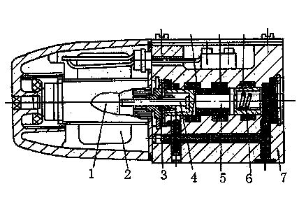
[0010] Such as figure 1 As shown, the electromagnetic reversing valve, the electromagnetic reversing valve, includes the armature 1, the coil 2, the push rod 4, the valve core 5 and the valve body 7, the push rod 4 and the valve core 5 are installed in the valve body 7, the push rod 4 and the The spool 5 is connected, the armature 1 is installed on the top of the push rod 4, the coil 2 is installed on the lower end of the armature 1, a sealing ring 3 is provided between the push rod 4 and the valve body 7, and a spring 6 is installed on the spool 5. The electromagnetic reversing valve increases the cross-sectional area of ​​the flow channel, which also increases the liquid flow, and changes the parameters of the electromagnet to reduce power consumption and increase the reversing frequency.


PUM


Abstract

The invention discloses a magnetic exchange valve which comprises an armature (1), a coil (2), a push rod (4), a valve core (5) and a valve body (7), wherein the push rod (4) and the valve core (5) are mounted inside the valve body (7), the push rod (4) is connected with the valve core (5), the armature (1) is mounted at the top of the push rod (4), and the coil (2) is mounted at the lower end of the armature (1). According to the magnetic exchange valve provided by the invention, the cross section area of a runner is increased, the liquid flow is increased, and parameters of an electromagnet are changed, so as to reduce power dissipation and increase direction-changing frequency.

Description

technical field [0001] The invention relates to an electromagnetic reversing valve. Background technique [0002] In the prior art, the electromagnetic reversing valve used in the hydraulic system is mainly composed of valve body, valve core, spring, electromagnet and other parts, which mainly solve the start, stop and direction control of the hydraulic actuator. There are common shortcomings such as oil leakage and low commutation frequency. Contents of the invention [0003] The object of the present invention is to provide an electromagnetic reversing valve. [0004] The technical solution adopted by the present invention to achieve the above purpose is: an electromagnetic reversing valve, including an armature (1), a coil (2), a push rod (4), a valve core (5) and a valve body (7). The push rod (4) and the valve core (5) are installed in the valve body (7), the push rod (4) is connected with the valve core (5), the armature (1) is installed on the top of the push rod ...

Claims


Application Information

Patent Timeline
Patent Type & Authority Applications(China)
IPC IPC(8): F15B13/02
Inventor 李新栋
Owner DALIAN QIANBAO CAST IRON FOUNDRY
Why Eureka
Try Eureka