locking combination carabiner
What is Al technical title?
Al technical title is built by PatSnap Al team. It summarizes the technical point description of the patent document.
A technology of combining hooks and shackles, applied in the directions of pipe supports, pipes/pipe joints/pipes, mechanical equipment, etc., it can solve the problems of not being able to install at large angles or even vertically, and the hooks cannot be locked and fixed, so as to achieve convenient combination and flexible use. Safety and high standardization effect
Active Publication Date: 2015-09-30
山东太极龙塑胶科技有限公司
View PDF7 Cites 0 Cited by
Summary
Abstract
Description
Claims
Application Information
AI Technical Summary
This helps you quickly interpret patents by identifying the three key elements:
Problems solved by technology
Method used
Benefits of technology
Problems solved by technology
[0005] The purpose of this patent is to solve the shortcomings of the current hook that cannot be locked and fixed after hooking, and the hook cannot be installed at a large angle or even vertically, and create a method that can lock and fix the hook after it is installed on the hook. A locking combination shackle that increases the scope of use of the hook and improves the safety, reliability, aesthetics and installation efficiency of its installation
Method used
Image
Click on the blue label to locate the original text in one second.
Reading with bidirectional positioning of images and text.
Examples
Embodiment Construction
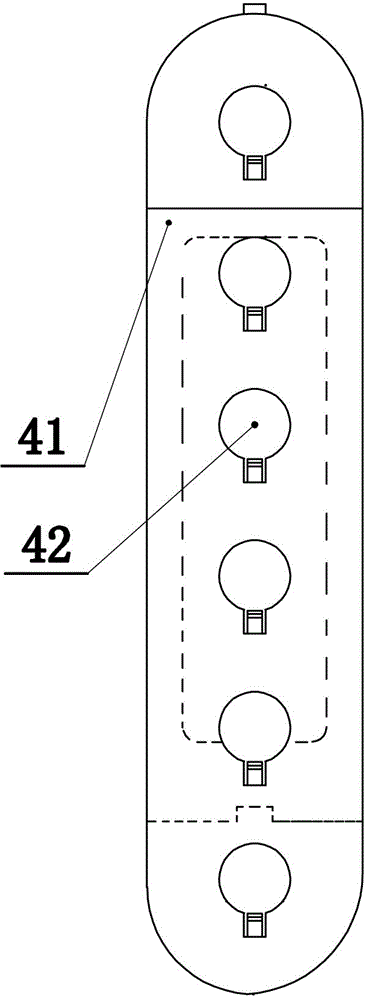
[0028] Hooking between the hook bodies 41. Such as Figures 10-13 As shown, when hooking a plurality of hook bodies, if there are many hanging objects, the first hook body 41 is fixed through the through hole 44 on the hook body 41, and the through hole 44 of the next hook body 41 is inserted into the On the cross post 45 on the last hook body 41, the elastic tooth 43 in the through hole 44 on the hook body 41 below is pressed down, and the elastic tooth 43 in the through hole 44 is connected with the cross post 45 of the last hook body 41. The anti-off teeth 47 cooperate to prevent disengagement, and complete the connection between the hook bodies; when disassembling, the pressure table 46 needs to be pressed down to separate the anti-off teeth 47 from the elastic teeth 43, and the disassembly can be completed by directly pulling out the next Hook body 41.
[0029] The locking block 21 is fixedly installed in the lower closure buckle 31 . Such as Figure 9 , The installat...
PUM
Abstract
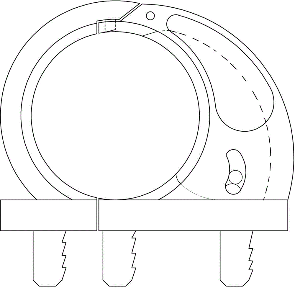
The invention provides a locking combined hook ring with the advantages that after a hanging connecting object is installed to a hook, the locking fixation is carried out through a certain mechanism, the use range of the hanging connecting object is enlarged, the safety, the reliability and the attractive appearance of the hanging connecting object are enhanced, and the installation efficiency is improved. The locking combined hook ring is characterized by comprising a hook body and a sealing buckle arranged on the hook body, wherein the upper end of the hook body is provided with a through hole, the lower end of the hook body is provided with a transverse post, installing holes are distributed in the middle of the hook body, the sealing buckle is formed by combining an upper sealing buckle and a lower sealing buckle, the upper sealing buckle comprises an upper hook ring and a first installing post, an upper sealing post is arranged on the tail end of the upper hook ring, the lower sealing buckle comprises a lower hook ring and a second installing post, the tail end of the lower hook ring is provided with a lower sealing hole matched with the upper sealing post, a locking block chamber is arranged between two side plates of the lower hook ring, the locking block chamber is an empty chamber with an arc-shaped groove, and a locking block is arranged inside the locking block chamber. The locking combined hook ring has the advantages that the combination is convenient, the appearance is attractive, reliability is realized, the use is more flexible and safer, the standardization degree is higher, the upper sealing block, the lower sealing buckle, the locking block and the like are arranged on the hook body of the product and are respectively processed and formed in one step, and the production efficiency is high.
Description
technical field [0001] The invention relates to a locking combination shackle used in industrial and mining enterprises for erecting cables, water, electricity and heating pipes and the like. Background technique [0002] At present, most of the hooks used in the installation of cables and pipes in industrial and mining enterprises are single-hook type and multi-hook type. Whether it is metal or non-metallic material hooks, the cables or pipes are directly hung on the hook body, because the cables Or the size of the pipe is different from the diameter of the hook, which is the looseness of the hook. Even if it is tied and fixed with cable ties, the hanger still exists in the hook because the diameter of the hook and the diameter of the hook are different. Looseness is unreliable, unsightly, and installation efficiency is low with cable ties. [0003] After long-term use and investigation of the hooks, the current hooks are all just put the hooks directly into the arc of the...
Claims
Application Information
Patent Timeline
Application Date:The date an application was filed.
Publication Date:The date a patent or application was officially published.
First Publication Date:The earliest publication date of a patent with the same application number.
Issue Date:Publication date of the patent grant document.
PCT Entry Date:The Entry date of PCT National Phase.
Estimated Expiry Date:The statutory expiry date of a patent right according to the Patent Law, and it is the longest term of protection that the patent right can achieve without the termination of the patent right due to other reasons(Term extension factor has been taken into account ).
Invalid Date:Actual expiry date is based on effective date or publication date of legal transaction data of invalid patent.