Intelligent monitoring system

A technology of intelligent monitoring system and refrigeration system, applied in heating and ventilation control system, signal transmission system, heating and ventilation safety system, etc., can solve problems such as waste of personnel

Inactive Publication Date: 2014-06-11
ZHEJIANG RUINENG COMM TECH
7 Cites 0 Cited by

AI-Extracted Technical Summary

Problems solved by technology

This will inevitably lead to...

Method used

Multi-mode air-conditioning controller D: multi-mode air-conditioning controller D comprises the collection of base station ambient temperature and comprises 6 temperature points such as outdoor temperature, return air temperature, each blower outlet temperature, mobile base station indoor ambient temperature, and air-conditioning There are three working modes, namely large air conditioner operation mode (C1 mode), small air conditioner operation mode (C2 mode) and water chiller operation mode (C3). According to different ambient temperatures, the air conditioner operation mode can be combined by the above three modes to form Multi-mode base station environment control to achieve the energy-saving effect of base station environment control. The RS485 bus output is connected to the DB9-F terminal 20 of the monitoring main module A to form an RS485 bus, and the information transmission between the base station environment information and the monitoring main module can be realized through a custom protocol.
[0023] As shown in Figure 1, the intelligent monitoring system of the mobile base station environment state includes a multimodal air-conditioning control module D, power information collection module B, monitoring main module A and GPRS communication module C. The information transmission network of the intelligent monitoring system consists of a two-layer network, that is, the RS485 environmental information collection network for collecting field information and the GPRS Ethernet remote information measurement and control network. The enterprise server software E establishes an Ethernet communication link with the GPRS communication module to realize the link management and information management of the monitoring network.
[0030] The power-down storage of the base station environmental status monitoring information is connected w...

Abstract

The invention provides an intelligent monitoring system, which is used for monitoring the environment state of a multi-source refrigeration system of a mobile base station. The intelligent monitoring system structurally comprises a monitoring main module, an electric energy information collection module, a GPRS (general packet radio service) communication module and a multi-mode air conditioning control module, wherein the monitoring main module is used for monitoring the environment state of the mobile base station. The intelligent monitoring system has the advantages that the base station environment information is transmitted to enterprise server software for analysis and management, in addition, relevant warning information is given out, meanwhile, the in-site parameters of the network intelligent monitoring system can be modified in a remote way through software, and the unattended operation of the base station is really realized.

Application Domain

Transmission systemsSpace heating and ventilation safety systems +3

Technology Topic

Electric energyEngineering +10

Image

  • Intelligent monitoring system
  • Intelligent monitoring system
  • Intelligent monitoring system

Examples

  • Experimental program(1)

Example Embodiment

[0021] In the following description, numerous specific details are set forth in order to provide a thorough understanding of the present invention. However, the present invention can be implemented in many other ways different from those described herein, and those skilled in the art can make similar promotions without departing from the connotation of the present invention. Therefore, the present invention is not limited by the specific embodiments disclosed below.
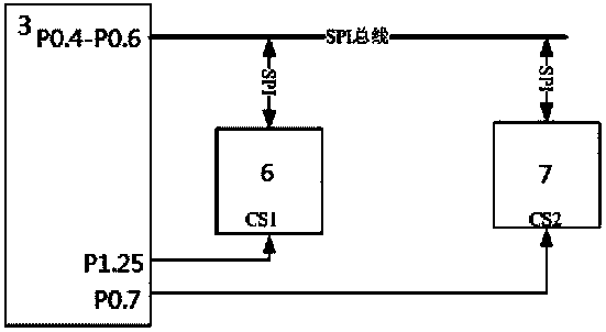
[0022] The invention includes: a monitoring main module A for monitoring the environmental state of the mobile base station, a power information acquisition module B, a GPRS communication module C, and a multi-modal air conditioning control module D, wherein:
[0023] like figure 1 As shown, the intelligent monitoring system for the environmental state of the mobile base station in structure includes a multi-modal air conditioning control module D, a power information collection module B, a main monitoring module A and a GPRS communication module C. The information transmission network of the intelligent monitoring system is composed of two-layer networks, namely, the RS485 environmental information acquisition network and the GPRS Ethernet remote information measurement and control network used to collect on-site information. The enterprise server software E establishes an Ethernet communication link with the GPRS communication module to realize the link management and information management of the monitoring network.
[0024] like Figure 2 to Figure 4 The monitoring main module A is revealed. The structure of the monitoring main module A is a three-layer backpack. The lower layer is the power layer A 3. The middle layer is the input/output layer A 2. The upper layer is the treatment layer A 1. Power plane A 3 and input/output layer A 2 between A 2 -A 3 Connector 28 is connected. Input/Output Layer A 2 and processing layer A 1 between A 1 -A 2 The connector 25 is connected. The main functions of monitoring main module A include mobile base station environmental status information collection, remote transmission of base station environmental information, provision of operator information transmission interface, intelligent monitoring system function expansion, switch input and output, and related auxiliary circuits such as power supply and filtering.
[0025] The functions are implemented as follows:
[0026] The base station environment state information collection uses the RS485 bus 29 to transmit the state of the multi-modal air conditioner control module D, the environment information (including the temperature information of each measurement point) and the air conditioner operating state through the input/output layer A using a customized communication protocol 2 The communication port is DB9-F interface 20, transmitted to MAX3485 RS485 bus driver 19, and then through A 1 -A 2 The connector transmits to the first communication port UART0 of the LPC2138 type processor 3. Monitor the first communication port UART0 of the processor LPC2138 of the main module A via A 1 -A 2 The connector 25 is connected with the RS485 bus driver 19, and the data collection of the base station environment information object is realized through the RS485 bus 29 and the self-defined communication protocol.
[0027] The remote transmission of the base station environmental information is performed by the second communication port UART1 of the processor 3 via A 1 -A 2 The connector 25 and the communication selection jumper 21 are finally connected to the first channel of the MAX3232 RS232 bus driver 24 . Convert the TTL communication signal into the RS232 level communication signal, and connect with the RS232 bus 32. Another port of the communication selection jumper 21 is connected with the TTL end of the MAX3485 RS485 bus driver 22 , and finally connected with the RS485 bus 31 through the communication port 23 . And thus connect with GPRS communication module C to realize remote transmission of collected information. Thereby, an Ethernet communication connection between the base station information and the enterprise server software E is formed, and the base station environment information is transmitted to the enterprise server software E for analysis and management, and relevant alarm information is given; at the same time, the base station network can be remotely modified through the software. The on-site parameters of the intelligent monitoring system are truly unattended in the base station environment.
[0028] The operator information transmission interface is provided by connecting the SPI interface of the processor 3 with the SC16IS762 type communication conversion chip 7 . P0.7 of processor 3 is used as a chip select signal to connect with CS chip select of communication conversion chip 7 to complete SPI addressing. The first communication port A of the communication conversion chip 7 passes through A 1 -A 2 The connector 25 is connected to the second port of the MAX3232 RS232 bus driver 24, and its RS232 level port is connected 30 to the RS232 bus 30 through the communication port 23, providing a channel for operators to obtain base station information.
[0029] The function expansion of the intelligent monitoring system is realized by the communication conversion chip 7 . The second communication port B of the communication conversion chip 7 is connected to the TTL level port of the MAX3485 RS485 bus driver 8, and the Rtsb output line of the communication conversion chip 7 realizes the flow control of the RS485 communication. The RS485 level port of the MAX3485 RS485 bus driver 8 provides an RS485 bus interface for function expansion through the function expansion communication terminal 9.
[0030] The power-down storage of the base station environmental state monitoring information is connected to the AT45D081D FLASH memory 6 through the SPI interface of the processor 3 . P1.25 of the processor 3 provides the chip select signal of the FLASH memory 6 . The processor 3 stores the monitoring data in the FLASH memory 6 according to the set rule, so as to achieve the purpose of power failure protection.
[0031] like Figure 5 As shown, the switch input signal is transmitted from the switch input port 12 through the resistor R 11 Connect with TLP521-2 opto-isolator 13 (pin 1). Resistor R6 It is connected in parallel with the opto-isolator 13 to achieve the purpose of protecting the opto-isolator. The output terminal (pin 8) of the opto-isolator 13 is connected through the resistor R 36 Connect to +5V power supply. At the same time, the opto-isolator 13 is connected to the LM339 type comparison filter 14 (pin 7). Compare filter 14 (pin 6) provides a compare reference voltage. Compare filter 14 (pin 1) on the one hand with the pull-up resistor R 51 connection, the other side via A 1 -A 2 The connector 25 is connected with the LED indicator and P0.30 of the processor 3 to realize switch signal input.
[0032] like Image 6 Shown discloses relay 17 switching the output circuit. P0.23 of processor 3 on the one hand with the diode of output indicator 5 (DS 13 ) is connected to the K pin of the 74HC04 type inverter 4 (pin 1) on the other hand. Inverter 4 (pin 2) via A 1 -A 2 Connector 25 with resistor R 17 connected to drive the transistor T 11 , and by T 11 To drive the relay 17, the control output of the relay 17 is realized.
[0033] like Figure 7 As shown, the input power supply of the main module A of the intelligent monitoring system is +12V, and the actual power supply required is +12V (for relay), +5V and +3.3V, etc. Introduced by the power port 27 DC12V input and diode (D 8 pin A) is connected via A 2 -A 3 Connector 26 with T 2 Fuse Connection, T 2 The other output of the fuse with capacitor C 1 And LM2575-5V switching power converter 35 (pin 1) connection. T 2 The other output of the fuse is simultaneously connected to the capacitor C 5 And LM2575-3.3V type switching power converter 36 (pin 1) is connected. LM2575-5V type switching power converter 35 (pin 2 and pin 4) with inductor H 1 , quick reply off D 1 and capacitor C 2 Constitute a switching oscillation output circuit, through C 3 , L 1 , C 4 The formed filter circuit outputs the stable DC5V power supply required by the system, and is processed by A 2 -A 3 Connector 26 (pin 3) provides 5V power to the system. LM2575-3.3V type switching power converter 36 (pin 2 and pin 4) with inductor H 2 , quick reply off D 2 and capacitor C 6 Constitute a switching oscillation output circuit, through C 7 , L 2 , C 8 The formed filter circuit outputs the stable DC3.3V power supply required by the system, and is processed by A 2 -A 3 Connector 26 (pin 5) provides 3.3V power to the system.
[0034] like Figure 8 As shown, a circuit diagram for implementing SPI addressing by the processor 3 is disclosed. The pin P0.4 of the processor 3 is set as the CLK signal of the SPI, P0.5 is the main input and slave output data signal, P0.6 is the main output and slave input data signal, which are respectively connected with the SC16IS762 type communication conversion chip 7 (pin 11. Connect with pin 12, pin 13), and connect with FLASH memory 6 (pin 1, pin 2, pin 8) to form an SPI bus network. P0.7 and P1.25 of processor 3 respectively provide chip selection signal for SC16IS762 type communication conversion chip 7 and FLASH memory 6 to realize SPI addressing.
[0035] like Figure 9 As shown, the circuit for RS485 bus protection is revealed. The communication signals RXD and TXD from processor 3 are connected to MAX3485 type RS485 bus driver 19 (pin 1 and pin 4), respectively. P0.31 of processor 3 is connected to MAX3485 type RS485 bus driver 19 (pin 2 and pin 3) as the flow control signal of the RS485 bus. MAX3485 RS485 bus driver 19 (pin 6, RS485-A signal) with resistor R 2 , R 3 , R 4 and capacitor C 3 connect, R 4 The other end with TVS tube D 2 , D 4 connect. MAX3485 RS485 bus driver 19 (pin 7, RS485-B signal) with R 1 , R 2 , R 5 and C 4 connect, R 5 Another segment with TVS tube D 3 , D4 connection, to achieve the protection of RS485 bus.
[0036] like Figure 10 As shown, the electric energy information collection module B is to realize the collection of electric energy meter information and send the package of the collected information to the monitoring main module A. The first communication ports UART0 (RXD, TXD) of the processor 54 are connected to the communication jumpers 55 (pin 4 and pin 3), respectively. Communication jumper 55 (pin 1) connects to MAX3232 type RS232 bus driver 57 (pin 10). Communication jumper 55 (pin 2) connects to MAX3232 type RS232 bus driver 57 (pin 9). The RS232 bus driver 57 (pin 7, RRXD; pin 8, RTXD) is connected to the power information acquisition bus port 58 (pin 4 and pin 5) and connected with the RS232 bus 61, respectively. Communication jumper 55 (pin 5) connects to MAX3485 type RS485 bus driver 56 (pin 4). Communication jumper 55 (pin 6) connects to MAX3485 type RS485 bus driver 56 (pin 1). The RS485 bus driver 56 (pin 6A and pin 7B) is respectively connected to the power information acquisition bus port 58 (pin 1 and pin 2) through the protection circuit and is connected with the RS485 bus 62 . The second communication ports P0.8 (TXD1) and P0.9 (RXD1) of the processor 54 are connected to the MAX3485 type RS485 bus driver 51 (pin 4 and pin 1). The pin P0.16 of the processor 54 is connected to the RS485 bus driver 51 (pin 2 and pin 3) as the RS485 bus flow control signal.
[0037] like Figure 11 As shown, the communication port of the multi-modal air conditioning control processor 67 is connected to the RS485 bus driver 66 (pin 1 and pin 4) of the MAX3485 type. The MAX3485 RS485 bus driver 66 (pin 6 and pin 7) is connected to the RS485 communication port 65 (pin 1 and pin 2) through the filtering and protection circuit, and is connected to the RS485 bus 29 to monitor the main module A and power information The acquisition module B constitutes a base station environment information acquisition bottom network.
[0038] Base station electric energy information collection module B: The base station electric energy information collection is connected with the electric meter through RS485 bus 62 (J3 port) to form an electric meter information communication link, and the DL/T645-1997 standard communication protocol is applied to realize the electric energy meter information to the electric energy information collection module B data exchange. The second communication port of the processor 54 is connected to the RS485 driver 56, and forms an information acquisition RS485 bus 29 with the monitoring main module A through the power supply and communication port 50, and realizes network addressing and information transmission by encoding the module address.
[0039] GPRS communication module C and enterprise server software E: The monitoring main module A establishes an Ethernet communication connection with the D820 GPRS communication module through RS232 bus 32, and uses the TCP protocol to send the information of the mobile base station to the enterprise server; the enterprise server software E sends each remote The GPRS communication connection of the server is stored in the database, and the remote information is collected to the server database by the method of time-sharing query, and the graphical display of the information and the alarm output are given.
[0040] Multi-modal air-conditioning controller D: Multi-modal air-conditioning controller D includes the collection of base station ambient temperature, including outdoor temperature, return air temperature, temperature of each fan outlet, and indoor ambient temperature of mobile base station. Mode operation, namely large air conditioner operation mode (C1 mode), small air conditioner operation mode (C2 mode) and water cooler operation mode (C3). According to the different ambient temperature, the air conditioner operation mode can be combined by the above three modes to form a multi-mode base station Environmental control to achieve the energy-saving effect of base station environmental control. The RS485 bus output is connected to the DB9-F terminal 20 of the monitoring main module A to form an RS485 bus. Through the self-defined protocol, the information transmission of the base station environmental information and the monitoring main module can be realized.
[0041] Although the present invention is disclosed above with preferred embodiments, it is not intended to limit the present invention. Any person skilled in the art can make possible changes and modifications without departing from the spirit and scope of the present invention. Therefore, the present invention The scope of protection shall be subject to the scope defined by the claims of the present invention.

PUM

no PUM

Description & Claims & Application Information

We can also present the details of the Description, Claims and Application information to help users get a comprehensive understanding of the technical details of the patent, such as background art, summary of invention, brief description of drawings, description of embodiments, and other original content. On the other hand, users can also determine the specific scope of protection of the technology through the list of claims; as well as understand the changes in the life cycle of the technology with the presentation of the patent timeline. Login to view more.
Why Eureka
Try Eureka