

Method for realizing split screen and electronic equipment
An electronic device, split screen technology, applied in the field of electronics, can solve the problems of only the traditional display switching function, AIO does not support PIP or split screen function, etc., to achieve the effect of good display effect and cost saving
- Summary
- Abstract
- Description
- Claims
- Application Information
AI Technical Summary
Problems solved by technology
Method used
Image

Examples
Embodiment 1
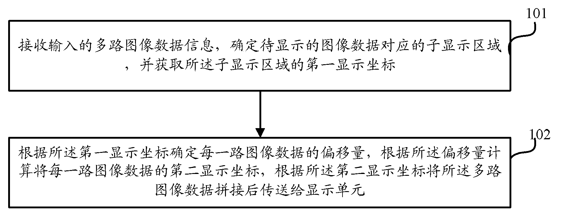
[0044] Embodiment one, as figure 1 As shown, the embodiment of the present invention provides a method for realizing split screen, and the specific implementation of the present invention will be described in detail below in conjunction with the accompanying drawings:
[0045] The method is applied in an electronic device, and the electronic device includes a display unit, and the display area of the display unit is divided into a plurality of sub-display areas (according to the existing split-screen conditions, it can be divided into two screens and four screens. ), the method specifically includes steps:
[0046] Step 101, receiving input multi-channel image data information, determining the sub-display area corresponding to the image data to be displayed, and acquiring the first display coordinates of the sub-display area;
[0047] In the embodiment of the present invention, the number of sub-display areas can be preset by the user in advance; it can also be determined acc...
Embodiment 3
[0058] Embodiment three, as Figure 5 As shown, in the specific use process, after the display data is determined, it may be necessary to insert a certain channel of image data for display, so the embodiment of the present invention also includes:
[0059] Step 501, when the newly inserted external image data is detected, obtain the first display area identifier included in the external image data;
[0060] In this embodiment, if there is new image data to be inserted, the electronic device first needs to detect whether the current split-screen mode can accommodate the newly inserted image data, and if so, directly display the newly inserted image data in the free sub-display area , but if not, two situations need to be distinguished:
[0061] Case 1. The newly inserted image data has specific requirements on the position of the sub-display area, that is, the newly inserted image data needs to be displayed in a specific area that already has display content;
[0062] Case 2:...
PUM
 Abstract
Description
Claims
Application Information