Device for decoupling antennas in compact antenna array and antenna array with the device

一种天线阵列、紧凑型的技术,应用在天线耦合、独立的无互作用天线组合、天线等方向,能够解决降低信噪比、空间相关性信道容量减小、增大天线空间/方向图相关性等问题

Active Publication Date: 2014-06-11
THE CHINESE UNIVERSITY OF HONG KONG
View PDF4 Cites 19 Cited by
  • Summary
  • Abstract
  • Description
  • Claims
  • Application Information

AI Technical Summary

Problems solved by technology

Such restricted spacing not only increases the spatial / pattern correlation between antennas, but also results in strong mutual coupling between antennas
High spatial correlation leads to channel correlation and reduced channel capacity, while strong mutual coupling leads to reduced radiation efficiency, which in turn reduces signal-to-noise ratio and ultimately reduces channel capacity

Method used


Image

  • Device for decoupling antennas in compact antenna array and antenna array with the device
  • Device for decoupling antennas in compact antenna array and antenna array with the device
  • Device for decoupling antennas in compact antenna array and antenna array with the device

Examples


Embodiment Construction

[0035] Hereinafter, embodiments of the present application will be described with reference to the accompanying drawings. Specifically, it is described in the following order: (1) structure of decoupling network, (2) setting of coupling coefficient, (3) effects and advantages, (4) experimental results, (5) dual-band decoupling network, and ( 6) Three-element decoupling network for three strongly coupled antennas.

[0036] Structure of the decoupling network

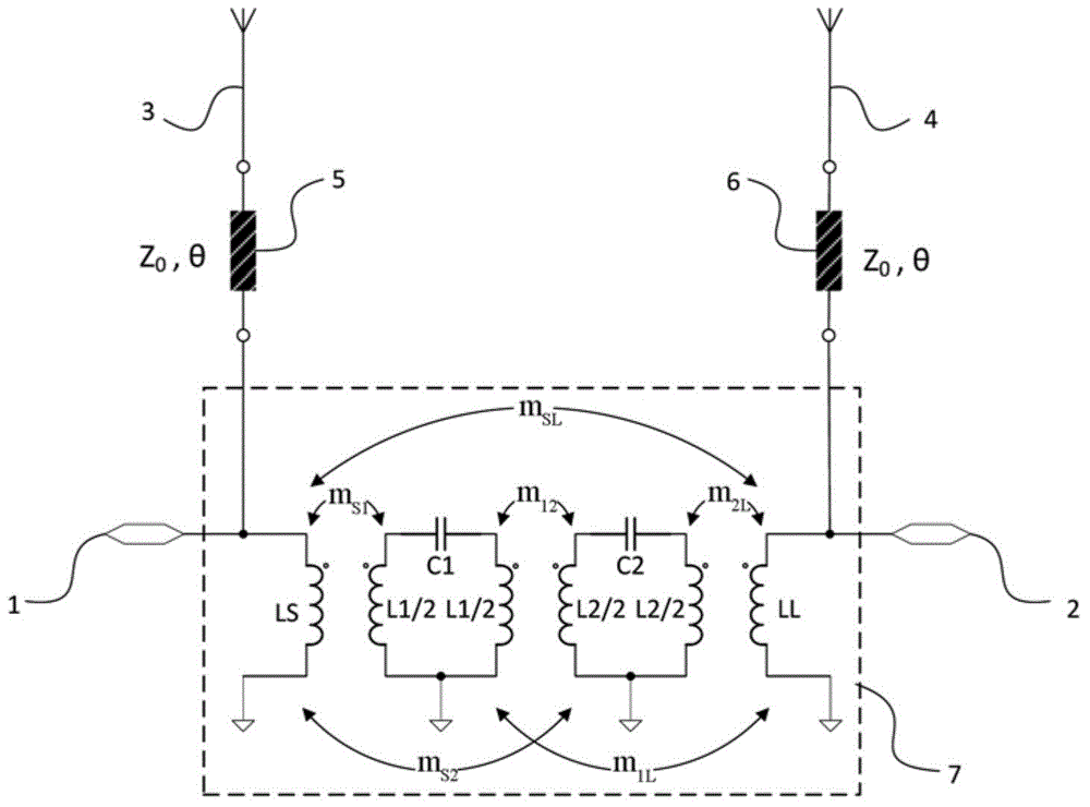
[0037] figure 1 A schematic diagram of a circuit according to an embodiment of the present application is shown. It is well known that a multi-antenna network comprises a number of closely arranged antennas. In the following, the application is explained by taking a two-antenna network comprising two closely arranged antennas as an example. It should be understood that the configurations discussed below may also be used for each two antennas in an antenna network comprising more than two antennas. It should also be...


PUM


Abstract

Devices and methods for decoupling two antennas in a compact antenna array and antenna arrays comprising the devices are disclosed. According to an embodiment, the device comprises a first resonator coupled with a source, the source being connected with a first antenna of the two antennas; and a second resonator coupled with the first resonator and a load, the load being connected with a second antenna of the two antennas, wherein the first and second resonators are configured so that a first coupling between the source and the first resonator, a second coupling between the first and second resonators, and a third coupling between the second resonator and the load are satisfied with a constraint that an isolation coefficient in a whole network composed of a first two-port network consisting of the two antennas and a second two-port network consisting of the first and second resonators in parallel approach zero as well as reflection coefficients of each port of the whole network are minimized.

Description

technical field [0001] The present application relates to antenna decoupling techniques and, in particular, to devices for decoupling two or more antennas in a compact antenna array and a compact antenna array having such a device. Background technique [0002] The rapid progress of next-generation communication systems has inspired the development of high-throughput, miniaturized and portable mobile terminals. According to the famous Shannon's theorem, in order to improve the channel capacity / throughput of a communication system, one way is to increase the system bandwidth, which has been widely adopted in the third and fourth generation mobile terminals. Another approach is to use multiple-input multiple-output (MIMO) technology. This technique uses multiple antennas at both the transmitter and receiver to multiply the channel capacity. Therefore, future high-speed mobile terminals require broadband and compact multi-antenna array systems. [0003] Since wireless commun...

Claims


Application Information

Patent Timeline
Patent Type & Authority Applications(China)
IPC IPC(8): H01Q1/52H01Q21/28
CPCH01Q1/523
Inventor 吴克利赵鲁豫杨立勤
Owner THE CHINESE UNIVERSITY OF HONG KONG
Why Eureka
Try Eureka