Motor rotor assembly

A technology of motor rotors and components, applied in the direction of magnetic circuit rotating parts, magnetic circuit shape/style/structure, etc., can solve the problems of large amount of magnetic ring materials, poor magnetic ring induction, complex structure, etc., and achieve good induction effect, The induction magnetic field is uniform and the effect of reducing interference

Active Publication Date: 2014-06-11
ZHONGSHAN BROAD OCEAN
View PDF6 Cites 6 Cited by
  • Summary
  • Abstract
  • Description
  • Claims
  • Application Information

AI Technical Summary

Problems solved by technology

[0002] The rotor assembly of a traditional brushless DC motor (BLDC MOTOR) generally includes a rotor core, a permanent magnet, a magnetic ring bracket and a magnetic ring. The permanent magnet is installed on the rotor core, and the magnetic ring bracket is connected to the rotor core. The ring is nested on the magnetic ring bracket. The structure is complicated, the installation

Method used


Image

  • Motor rotor assembly
  • Motor rotor assembly
  • Motor rotor assembly

Examples


Embodiment 1

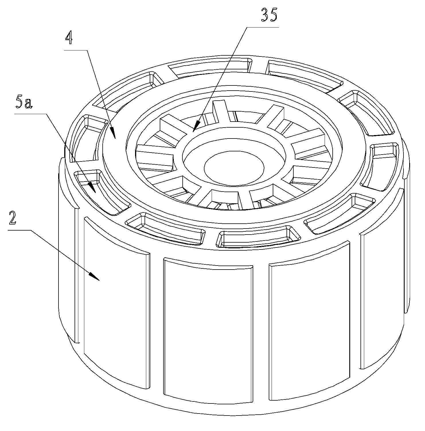
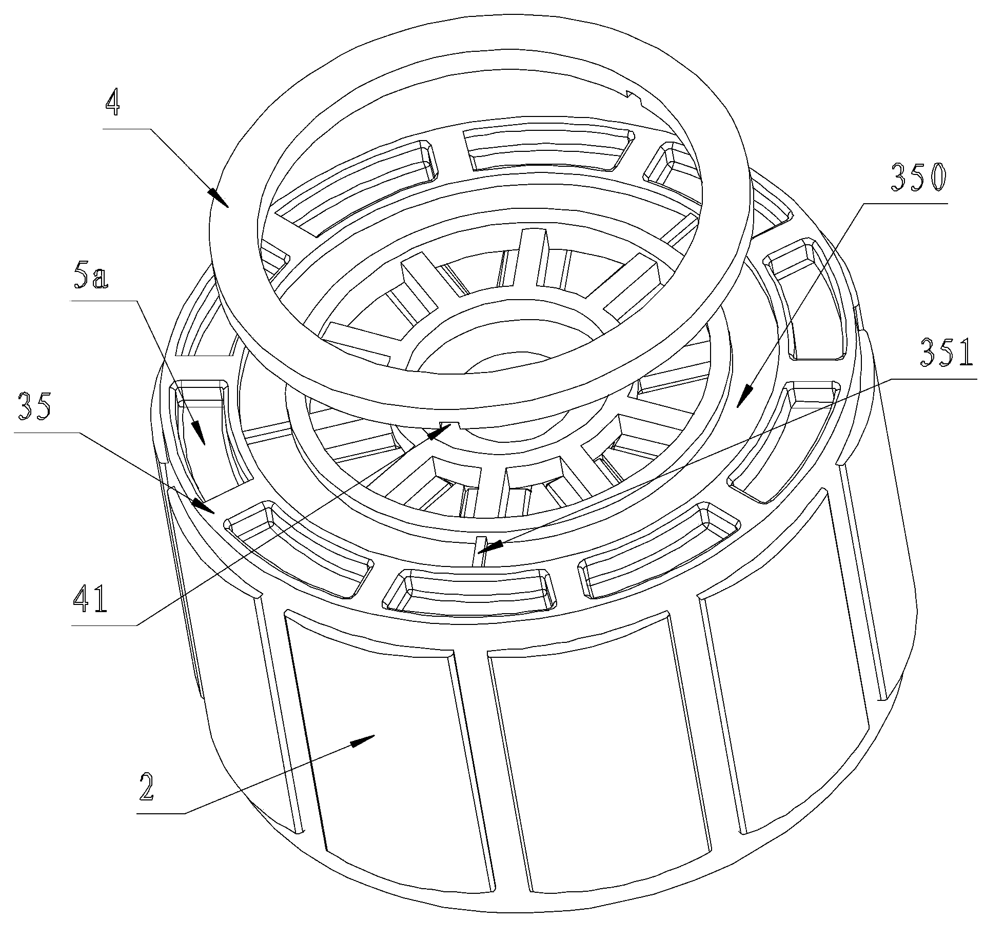
[0030] Embodiment one: if figure 1 and Figure 8 As shown, the present invention is a motor rotor assembly, including a permanent magnet 1, a rotor core 2 and a magnetic ring 4, and the rotor core 2 includes an annular ring 22 provided with a central axis hole 21 and protruding from the outer side of the annular ring 22 A plurality of magnetic conductive blocks 23, through holes 27 are opened on the magnetic conductive blocks 23, radial grooves 24 are formed between two adjacent magnetic conductive blocks 23, the permanent magnets 1 are embedded in the radial grooves 24, and the rotor core 2 An end plate 35 and a bottom plate 36 are respectively injection-molded on the end face and the bottom face of the end plate 35 and the bottom plate 36 are connected into a whole through the connecting column 37 passing through the through hole 27, and an annular groove 350 is arranged on the end face of the end plate 35, and the magnetic ring 4 Embedded in the groove 350 li.

Embodiment 2

[0031] Embodiment two: if figure 2 As shown, on the basis of Embodiment 1, the following technical features are added: a number of clamping blocks 351 protrude from the bottom of the groove 350 and the end plate 35 , and the clamping blocks 351 are embedded in the clamping groove 41 opened on the bottom surface of the magnetic ring 4 .

Embodiment 3

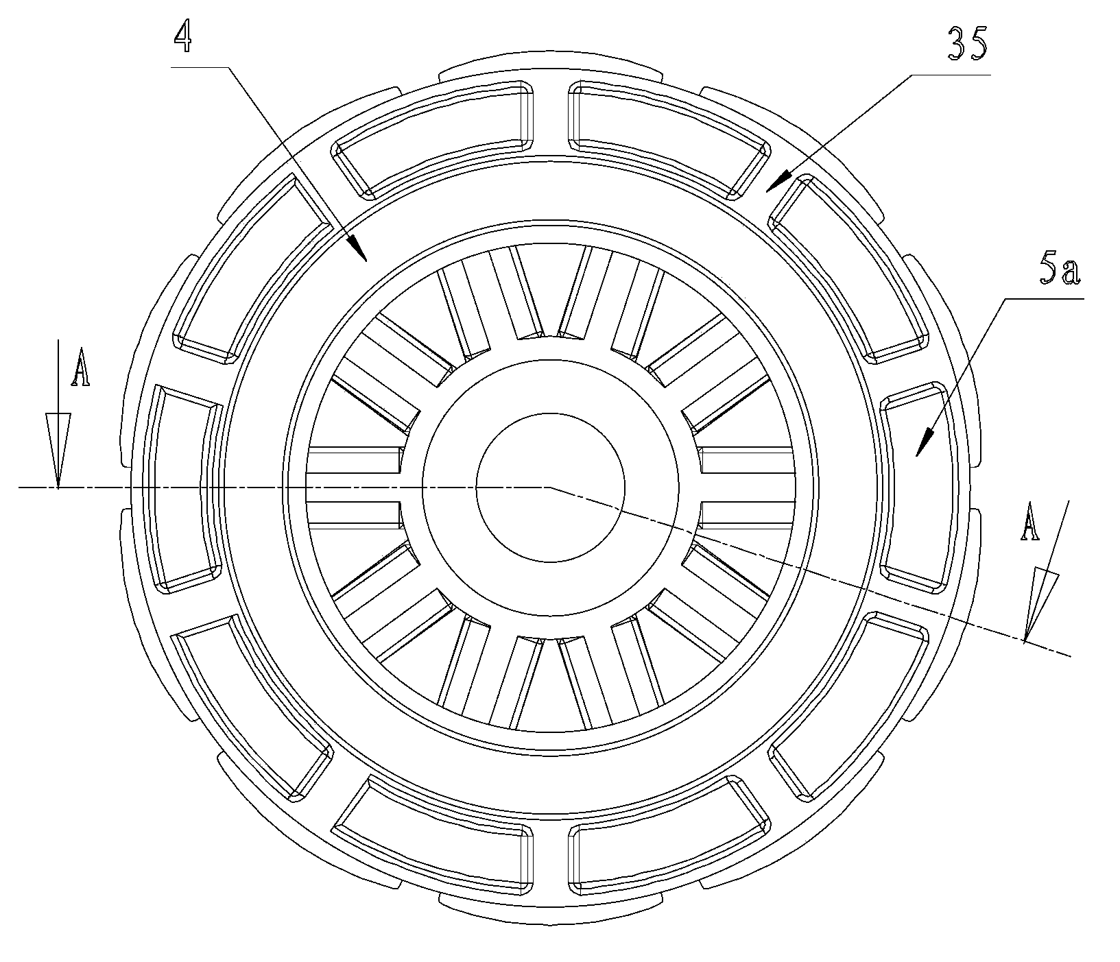
[0032] Embodiment three: as Figure 4 As shown, the following technical features are added on the basis of Embodiment 1 or Embodiment 2: the magnetic ring 4 is concentric with the central shaft hole 21 , and the magnetic ring 4 is adsorbed by the rotor core 2 and tightly attached to the end plate 35 .


PUM


Abstract

The invention discloses a motor rotor assembly. The motor rotor assembly comprises a permanent magnet, a rotor iron core and a magnetic ring. The rotor iron core comprises an annular ring and a plurality of permeability blocks, wherein the annular ring is provided with a center axle hole, and the permeability blocks protrude out of the outer side of the annular ring, through holes are formed in the permeability blocks, a radial groove is formed between every two adjacent permeability blocks, the permeability blocks are embedded into the radial grooves, the end face and the bottom face of the rotor iron core are provided with an end plate and a bottom plate in an injection molding mode respectively, the end plate and the bottom plate are connected into a whole through a connecting column penetrating through the through holes, the end face of the end plate is provided with an annular groove, and the magnetic ring is embedded into the annular groove. The motor rotor assembly is simple in structure, easy to install, and good in inducting effect, the magnetic ring materials are saved, and cost is reduced.

Description

Technical field: [0001] The invention relates to a motor rotor assembly, which belongs to the field of DC brushless motors. Background technique: [0002] The rotor assembly of a traditional brushless DC motor (BLDC MOTOR) generally includes a rotor core, a permanent magnet, a magnetic ring bracket and a magnetic ring. The permanent magnet is installed on the rotor core, and the magnetic ring bracket is connected to the rotor core. The ring is nested on the magnetic ring bracket. The structure is complicated, the installation is troublesome, and the induction of the magnetic ring is poor. However, the end-face induction structure with better induction effect is adopted. The magnetic ring is usually a disc type. There is a shaft hole in the center of the magnetic ring and the motor shaft. In combination, the amount of material used for the magnetic ring is large, the utilization rate is low, and the cost is high. Invention content: [0003] The purpose of the present inven...

Claims


Application Information

Patent Timeline
IPC IPC(8): H02K1/27
Inventor 潘明攀范建明
Owner ZHONGSHAN BROAD OCEAN
Why Eureka
Try Eureka