Fluid stream hydrodynamic separator with high flow bypass

A technology of flow rate and flow flow, applied in the field of hydraulic separator unit, which can solve problems such as layout blockage

Active Publication Date: 2014-06-11
WDD ENG
View PDF10 Cites 1 Cited by
  • Summary
  • Abstract
  • Description
  • Claims
  • Application Information

AI Technical Summary

Problems solved by technology

[0006] These arrangements have the disadvantage of clogging, as retained waste material (e.g. p

Method used


Image

  • Fluid stream hydrodynamic separator with high flow bypass
  • Fluid stream hydrodynamic separator with high flow bypass
  • Fluid stream hydrodynamic separator with high flow bypass

Examples


Embodiment Construction

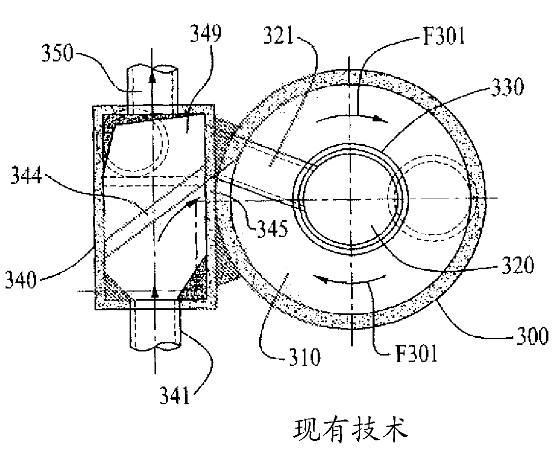
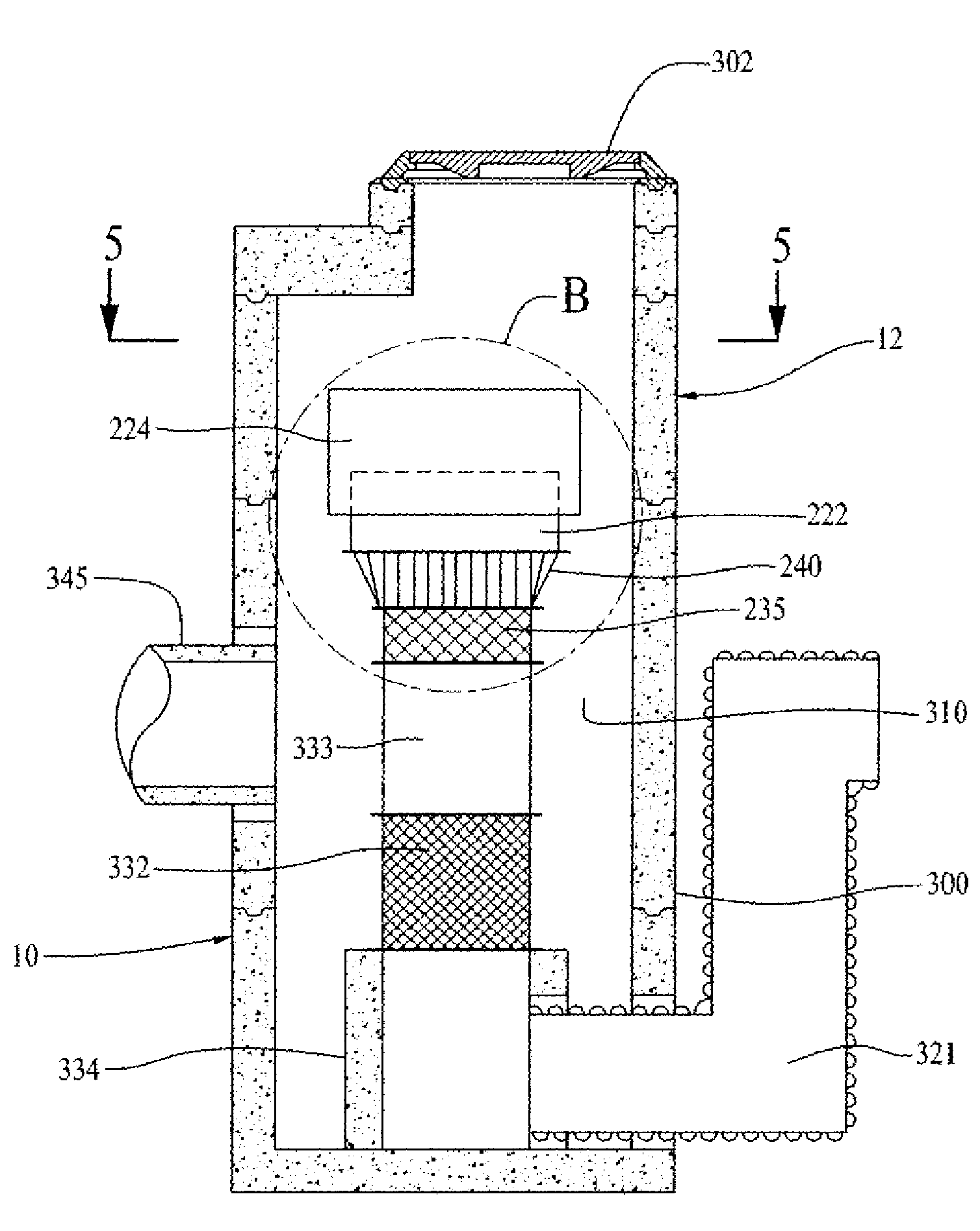
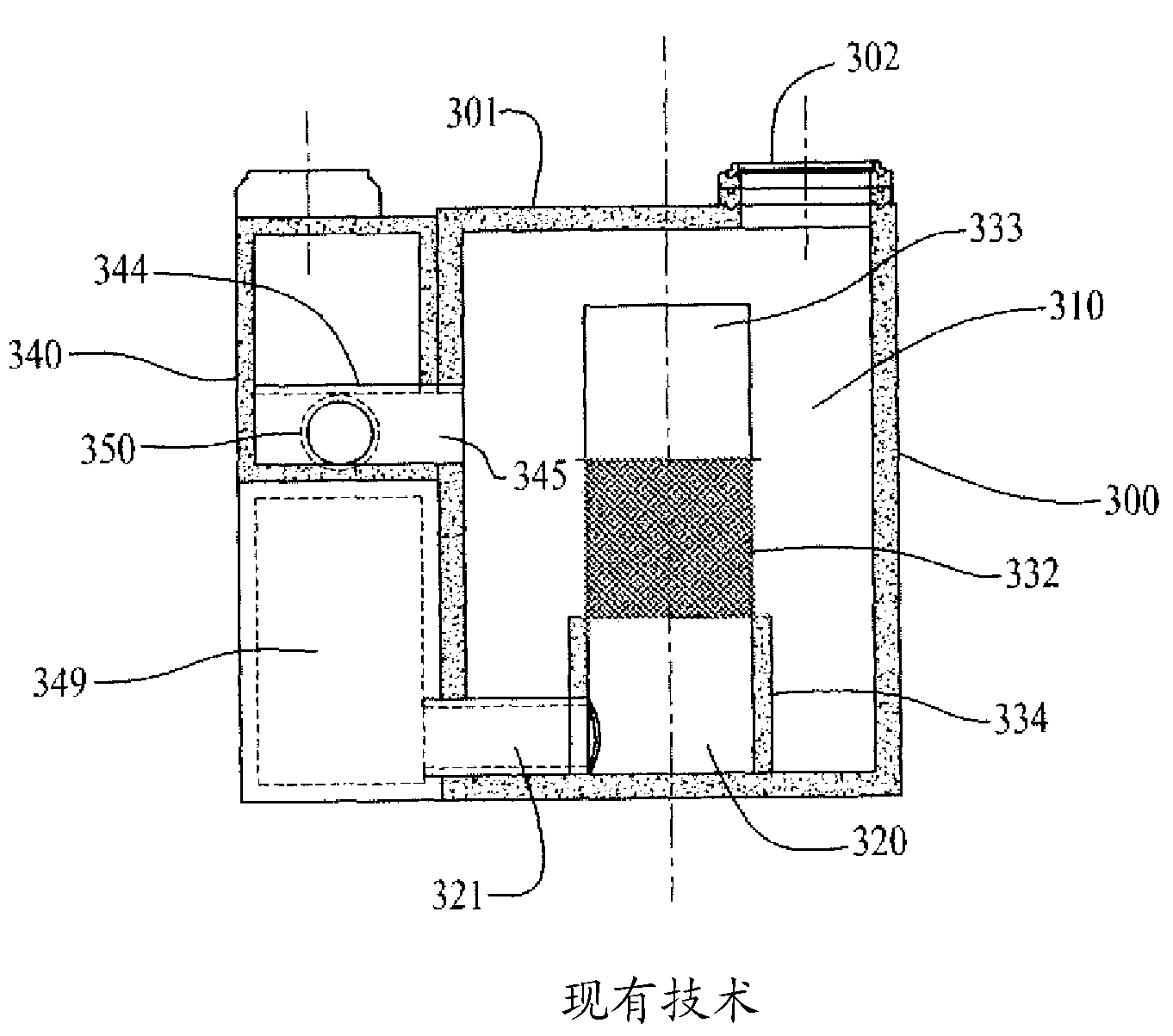
[0018] A hydraulic separator is described and illustrated herein for use in separating solid matter from liquid surface water streams, such as urban and industrial storm runoff containing waste materials. This structure is typically used to separate debris from an incoming stream before more delicate processing can be applied to the flowing stream. separator 10 (shown in Figure 3-6 Middle) includes an upper extension 12, referred to herein as the Quad Bypass Tower. This construction is a prior art structure (eg figure 1 and 2 shown in ) is an improvement over that.

[0019] refer to figure 1 , the barrier plate 333 comprises a solid walled hollow cylinder mounted on top of the main screen cylinder 332 which can be made porous by expansion, perforation, stamping, slotting or otherwise to Sieve material is provided. The rise of the top of this cylinder is set such that there is a relative height of about 1 to 2 feet above the desired water rise for flow across the bypas...


PUM


Abstract

A system for separating waste materials from a flowing stream of surface water comprises a vertical cylindrical vessel (300) and a vertical structure (330) within the cylindrical vessel. The vertical structure comprises an overflow structure with stacked filtering elements (235, 240) and weirs (222,224), sized to accommodate normal and increased fluid flow for abnormally high surface water flow conditions. The flowing stream containing waste material under normal flow conditions enters the vessel and passes through a filtering wall portion (332) in a lower section of the vertical structure and exits through an effluent pipe (321). Under higher flow conditions the water flows through the overflow structure mounted on top of the lower cylindrical structure which still filters some of the waste material out of the stream of surface water prior to discharge into the effluent pipe.

Description

[0001] Cross References to Related Applications [0002] This application claims the benefit of US Provisional Application 61 / 525650, filed August 19, 2011. technical field [0003] The present invention relates to hydrodynamic separator units designed to separate solid matter from surface water fluid flows into and through the unit under normal and abnormally high fluid flow conditions. Background technique [0004] An example of a prior art hydraulic separator is shown in US Patent No. 5,788,848. This patent shows a system comprising an inner and an outer non-concentric cylinder, the inner cylinder comprising a sieve section (sieve separator). The debris-laden stream is fed to the interior space within the inner cylindrical sieve separator; the material contained therein is retained inside and below the inner cylinder while the fluid flows from the inside of the inner sieve cylinder to the annular space between the inner and outer cylinders, and away from the surroundin...

Claims


Application Information

Patent Timeline
IPC IPC(8): E03F5/14B01D35/147
CPCE03F5/14B01D36/04B01D2221/12C02F2103/001E03F5/0403E03F5/0404
Inventor W.G.施泰因
Owner WDD ENG
Why Eureka
Try Eureka