Capping lifting mechanism, capping device and capping machine

A lifting mechanism and capping technology, which is applied in the directions of tightly capping containers with lids, packaging, conveyors, etc., can solve problems such as the impact of drug quality, the impact on bottle delivery efficiency, and the easy occurrence of bottle frying, so as to avoid pollution problems and ensure The effect of bottle feeding efficiency and improving operation convenience

Active Publication Date: 2014-06-18
TRUKING TECH LTD
View PDF5 Cites 4 Cited by
  • Summary
  • Abstract
  • Description
  • Claims
  • Application Information

AI Technical Summary

Problems solved by technology

The dial transmission mechanism usually includes a bottle feeding dial and a bottle feeding fence. The bottle feeding fence is placed outside the bottle feeding dial, and a bottle feeding channel is formed between the bottle feeding fence and the bottle feeding dial. The bottles are output sequentially by rotation, and the bottle auger of the auger transmission mechanism is used to separate the bottles at a certain distance, so that they can be better conveyed into the dial wheel or other transmission mechanisms. The installation position of the bottle auger is fixed. If the installation position of the bottle auger and the bottle auger is not accurate, it will easily cause the bottle body to be misaligned when it enters the bottle auger and the bottle auger, thereby causing the bottle to be squeezed. , it is easy to have bottle blowing phenomenon, once the bottle blowing phenomenon occurs, not only need to stop the machine to clean up the broken bottle, which affects the efficiency of bottle delivery, but also has a serious impact on the quality of the medicine in the bottle before and after the blown bottle appears

Method used


Image

  • Capping lifting mechanism, capping device and capping machine
  • Capping lifting mechanism, capping device and capping machine
  • Capping lifting mechanism, capping device and capping machine

Examples


Embodiment Construction

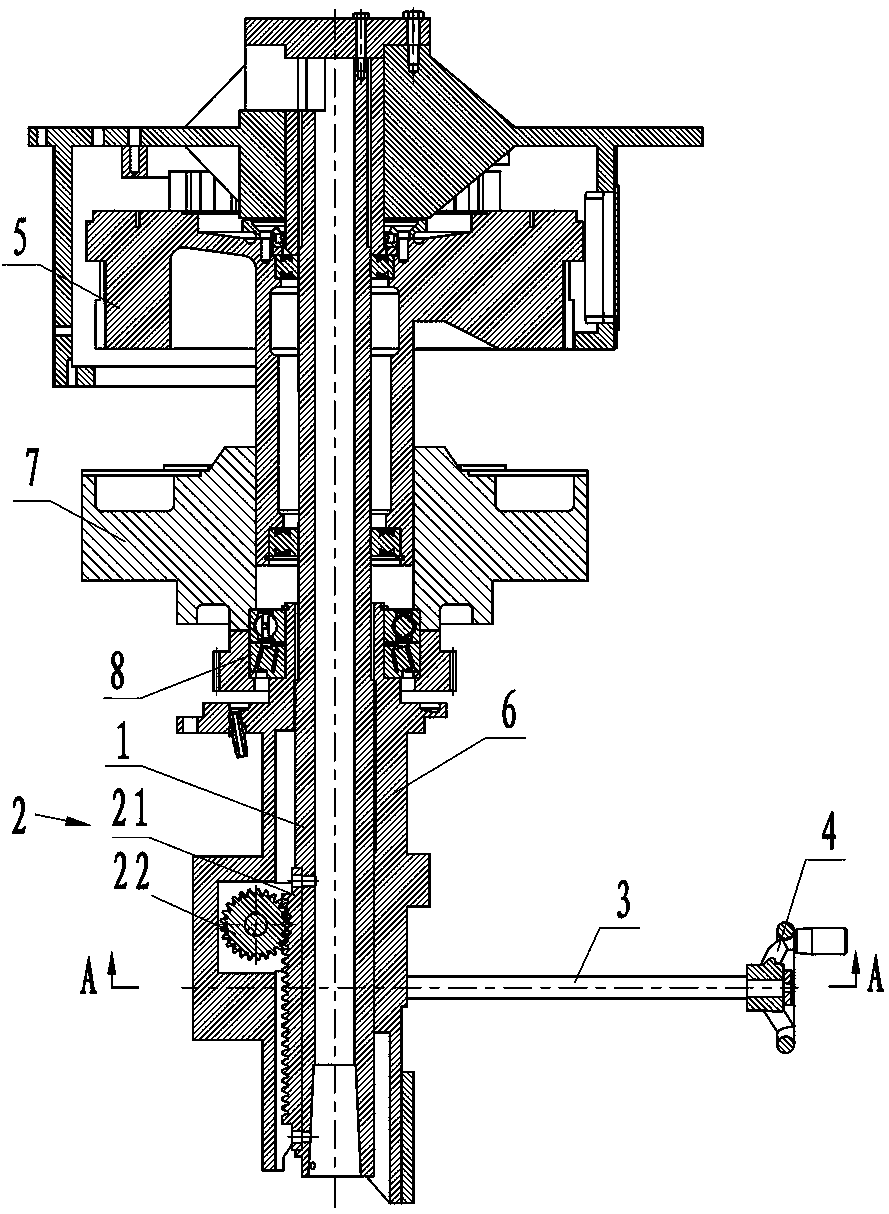
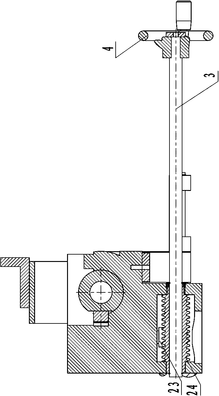
[0029] figure 1 , figure 2 It shows an embodiment of the capping and lifting mechanism of the present invention, which includes a capping main shaft 1 and a lifting assembly 2 that drives the capping main shaft 1 to move up and down. 23. The worm 24 and the rack 21 are fixed on the capping main shaft 1, the gear 22 and the worm wheel 23 are coaxially fixed, the worm wheel 23 is driven by the worm 24, the worm wheel 23 drives the gear 22, and the gear 22 drives the rack 21 to drive the capping The main shaft 1 moves up and down to realize the lifting adjustment of the capping part 9. The structure is simple and compact; since the worm gear and the rack and pinion have self-locking functions, the self-locking parts of the lock nut are omitted, which effectively avoids the need to adjust the capping main shaft. 1 height position, the cumbersome process of adjusting the position of the main shaft by rotating and loosening the lock nut, through the cooperation of the worm gear an...


PUM


Abstract

The invention discloses a capping lifting mechanism, a capping device and a capping machine. The capping lifting mechanism comprises a capping main shaft and a lifting assembly for driving the capping main shaft to ascend and descend, wherein the lifting assembly comprises a rack and a gear which are meshed with each other, and a worm gear and a worm which are meshed with each other; the rack is fixed to the capping main shaft; the gear and the worm gear are arranged coaxially and fixedly. The capping device comprises an upper pressure head assembly, a bottle supporting sleeve assembly, a capping main shaft locking mechanism for locking the capping main shaft, and the capping lifting mechanism, wherein the upper pressure head assembly is fixedly arranged on the capping main shaft; a capping component is arranged along the circumferential direction of the upper pressure head assembly; the capping main shaft sleeves in the bottle supporting sleeve assembly. The capping machine comprises the capping device and a bottle conveying device for conveying bottles, wherein the bottle conveying device comprises a packing auger conveying mechanism and a wheel shifting conveying mechanism which are connected in sequence. The capping lifting mechanism, the capping device and the capping machine have the advantages of simple and compact structure, convenience in adjustment and operation and high working efficiency.

Description

technical field [0001] The invention mainly relates to the field of capping, in particular to a capping lifting mechanism, a capping device and a capping machine. Background technique [0002] In the field of food and pharmaceutical packaging machinery, in order to ensure the airtightness of the bottle after packaging and the quality of the item during the storage period, a capping device is usually used to cap the bottle. The capping device is adapted to the capping of different bottles. Cap height requirements, usually equipped with a lifting mechanism for the lifting and adjusting of the capping parts, the existing capping lifting mechanism mainly includes the capping spindle connected with the capping parts, the lock nut and the rotating screw rod. position, it is necessary to loosen the lock nut and adjust the position of the capping spindle by rotating the screw mandrel, and then adjust the height of the capping parts. Since the lock nut and the rotating screw rod nee...

Claims


Application Information

Patent Timeline
Patent Type & Authority Applications(China)
IPC IPC(8): B67B3/00B65G33/02B65G33/24B65G29/00
Inventor 刘建勇陈勇
Owner TRUKING TECH LTD
Why Eureka
Try Eureka